Monday, May 14, 2018

Review of the Keysight DSO1102G relative to the Tektronix TBS 1202B-EDU


PROD-2766207-01.jpg
I recently received a new oscilloscope, the Keysight DSO1102G, for my workbench. I’ve had the Tektronix TBS1202B-EDU on my desk for a long while. Having never read through its manual I thought now would be a good time do a thorough read of both manuals. This would give me a better and more complete understanding of these two oscilloscopes. It would also allow me to have a greater appreciation of the differences between the two oscilloscopes without missing anything.

Out of the box these two oscilloscopes are truly an unfair comparison. Tektronix’s offering is an oscilloscopes and nothing more. While it does allow for courses to be uploaded to the unit, it is still just an oscilloscope. Keysights offering has multiple instruments built in. These include, serial bus decoding, wave generator and frequency response analyzer. The only reason to compare them is how their respective companies market them, they are both offered as entry level instruments. It will therefore be with this in mind that we will review these two instruments.

Documentation

Since both are packaged pretty much the same, the review will start with the documentation. Tektronix has taken the approach, this is for beginners and have written their user manual as such. The first ~70 pages, out ~170, explain how to use the instrument in a detail, that includes use cases and how certain measurements should be made. While helpful, this makes the likeliness of someone taking the time to fully familiarize themselves with the instrument less likely. On the other hand Keysight has chosen to just explain what functionality is included and how to access it. When needed, further explanation is provided. This minimalist approach along with the scopes built in help, makes the ~90 pages of the user manual that much easier to read. Keysight’s approach includes placing the information where you need it most, on the scope itself. This information is accessed by holding down the function key in question for a few seconds.

Unfortunately even with this well intending approach and built in help there are some functions that could use a clearer and slightly more in depth explanation. This includes the math function’s two functions (f(t), g(t)) and what the differences are between them. The notes on FFT functionality do not explain how to set the resolution and span. Masking is probably the best example of missing or shorthanded information. A diagram along with the code segment and an explanation tying the two together would have made this section more useful. One other missing piece of information noticed is how to use the trigger setup RxY:Data, TxY:Data and if this is even possible ([Trigger] > Trigger Type > Trigger Setup > Trigger Rx Start, when [Bus] > Mode = UART/RS232).

From this perspective the manual from Tektronix is some what better as every function is discussed in greater detail and explains clearly how to get each function to work. It should however be noted that in both manuals there was some functionality that either did not work as described or was not accessible.

Front Panel

At first glance the front panel of both units have a similar appearance with the Keysight having a slightly cozier feel compared to that of Tektronix. This likeness is quickly dismissed after spending time using the oscilloscopes. The cozy feel felt with the Keysight is due to the 42 buttons and knobs (51 functions) compared with the 35 (38 functions) on the Tektronix. The additional 7 function buttons allow for quicker and more intuitive access. These include a display button that allows such things as persistence to be quickly accessed during debugging sessions. A dedicated knob for cursor control allowing you to quickly take measurements of the the waveform being analyzed. There are also buttons for the added functionality (WaveGen, Bus and External Trigger) but, this applies to both instruments as the Tektronix has “course” and “function” buttons to access course material and the frequency counter. One really nice addition on the Keysight is the back button. This allows you to move seamlessly through menus without needing to go back to the top every time you want to go up one level.
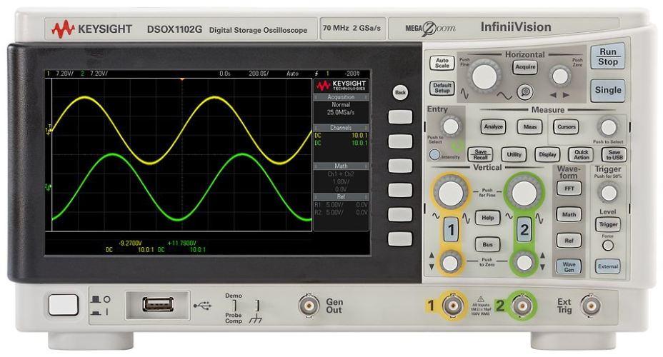
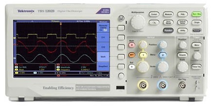
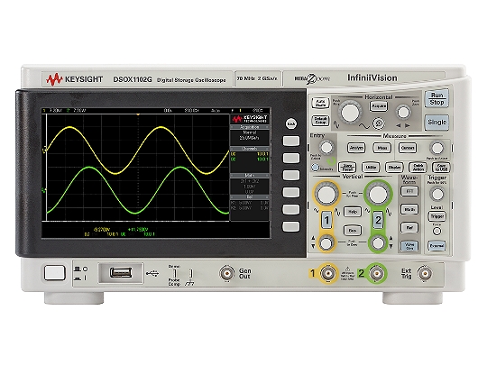
Keysight DSOX1102G next to the Tektronix TBS1202B-EDU

Display

Turning on the instruments brings the 7” displays to life. There is a noticeable difference between the two displays. Keysight’s is both sharp and clear with a nice update rate that makes visualizing waveforms a simple matter. While Tektronix’s display is not particularly hard to see or poor, there is definitely noticeable twitching in the displayed waveforms. Whether this is due to a slow update rate or because the internal processor can't keep up is unclear. You’ll also notice that even though both have 7” of real estate, Keysight reserves approximately an inch for information such as sample rate, probe attenuation, math equation and reference waveform information. While this does allow for the full waveform to be visible even with the information displayed it does change the screen size from 7” to a more realistic 6”. Tektronix, on the other hand overlays this information on the side hiding part of the waveform while this information is visible. Other noticeable differences are with the lighting. Keysight’s display settings work more like a phosphorus oscilloscope where the intensity only affects the waveform. The intensity of the grid lines are set separately. Tektronix however has decided to tie all of these together and only have one setting “backlight”. This doesn't allow for any “tuning” of the waveform like on older phosphorus scopes or to alter the contrast between various parts of the display.

Analog Input

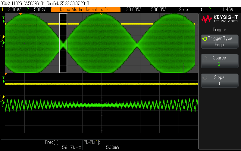
The main function of any oscilloscope is its ability to display input waveforms accurately and reliably. With the advertised specifications of the Tektronix oscilloscope surpassing that of the Keysight’s I was sure that Tektronix would outperform Keysight. In order to test the analog functionality, the test signals from each scope were used. Since the test signals are derived from the scopes internal clock this should be an acceptable waveform to test each scopes functionality as well as how well each function works. Unfortunately this quickly revealed differences between the abilities of the two scopes. Tektronix’s ability to keep up with the sample waveform was noticeably labourd. The inability to clearly sweep the signal made it obvious there is some memory or processing limitations preventing a clear waveform from being displayed. Another issue noticed, increasing the time base can introduce aliasing. The square wave with a measured period of 1ms using a time base of 50 ms/div, measured 100 ms using a time base of 250 ms/div. On the other hand the Keysight had no issues with either of these two scenarios. Keysight shows the waveform as a blur at the larger timebase, which at this time base it is. Zooming in on the waveform, the period measures 990 µs compared to the previous 992 µs. For someone familiar with the Tektronix scope, these issues may not be a big problem. Since these scopes are aimed at beginners and students, this can conceivably lead to incorrect measurements and a lack of understanding of the concept being taught.


A feature often used to prevent issues such as these is autoset. It should be noted, both Keysight and Tektronix depart from the documentation with regards to this function. Auto scale/set on the two scopes favors different setup parameters. Regardless of what is stated, if there is a valid signal on both channels, Keysight always favours setting up the scope using channel 1 and Tektronix channel 2. Tektronix has taken the autoset one step further than just stabilizing the waveform on the display. A quick press of the autoset button brings up a menu if the waveform being sampled is recognizable. A square wave, for example, gives you the option to see multiple periods, a single period or just the rising/falling edge. If, however, you hold the key down for an extended period, a new menu is displayed. This menu allows you to turn on/off autoranging as well as to select if you want just one or both the vertical and horizontal axis to be auto scaled.

Trigger

An important function of any scope is the trigger. Allowing the user to “freeze” the waveform when just the right portion comes past is what makes a scope useful. However, not all triggers are created equal. Keysight offers 7 triggering options compared to 3 from Tektronix. Offered by both scopes are; edge triggering (rising, falling and alternating/either), pulse width and video (NSTC, PAL and SECAM). Keysight added to this list, pattern matching, rise/fall time, setup and hold and triggering on serial events. Pattern matching allows you to specify a digital value each of the three channels (1, 2 and External) should have to initiate an event. The rise/fall time allows you to specify the time that a signal either rises from 10% - 90% or falls between these values. Triggering on a serial event allows for specific packets to be used as triggers. Also with a range of serial protocols implemented (CAN, I2C, LIN, SPI or UART/RS232) this feature has a lot of potential to resolve issues quickly.

Because not all signals are clean, both companies offer various pre-filters that can be applied to the input signal. These filters include noise rejection, HF rejection and LF rejection, to clean up the signal and improve triggering. Tektronix only allows for one filter to be used at a time. Keysight on the other hand allows for the stacking of these filters (in what order they are applied is unclear). Unfortunately with Keysight it's not clear what the signal you are triggering on looks like. This is because there is no way to easily view the signal being fed to the trigger circuit. Tektronix provides this ability by holding the trigger button for longer than 5 seconds. While not a major issue, it's helpful to know if the filters being applied are helping or potentially hurting your trigger acquisition.

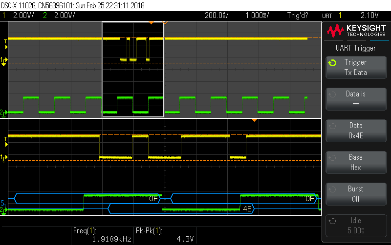
Keysight DSOX1102G triggering on I2C and UART signals respectively

Waveform Zoom

The zoom function offered by Keysight and Tektronix allows a user to examine parts of the waveform in greater detail. Implementations between the companies shows a varying focus on how they perceive their customers using this function. Keysight locks the waveform’s scale and horizontal position in place. The horizontal scale and position knobs are then used to zoom in/out on the waveform and shift the area of zoom respectively. Tektronix assumes the user may not just want to shift the waveform and zoom, but may want to change the time base or shift the trigger time value. For this reason Tektronix has kept the original functionality assigned to the horizontal controls. In order to zoom or to shift the magnified area, the multipurpose knob is used. Pressing in on the knob switches between altering the scale and the position of the zoom area.

This becomes more noticeable when you attempt to take measurements or change other settings while in zoom mode. Keysight keeps the cursors accessible (you still use the cursor knob) as well as all other functions such as math, FFT and Reference Waveforms. Although Tektronix does provide access to the math and reference waveforms (FFT terminates the magnified view) the math waveform is displayed but the reference waveforms are not. It would therefore appear Tektronix assumes the user is just interested in getting a closer look at the waveform. Keysight on the other hand assumes the user may want to do more while zoomed in. This includes taking more precise measurements with the coursers, compare sections of the waveform to a reference waveform or even look in detail at parts of the FFT, all of which is not possible on the Tektronix.

Math, FFT & Reference Functions

Math Function

The math and FFT functions also display noticeable differences between the two scopes. With regards to the math function, Keysight has seven operations available, addition, subtraction, multiplication, division, FFT (|x|), FFT (𝛉) and low pass filter (1Hz - 100MHz). There is also a secondary (internal function) that can be used for the FFT to select internal operations (addition, subtraction and multiplication) to be applied to the channels before the FFT is applied. Tektronix only provides three of these namely, addition, subtraction and multiplication. While the other operations might seem unnecessary, when working with analog circuits theses operations can be and are helpful.
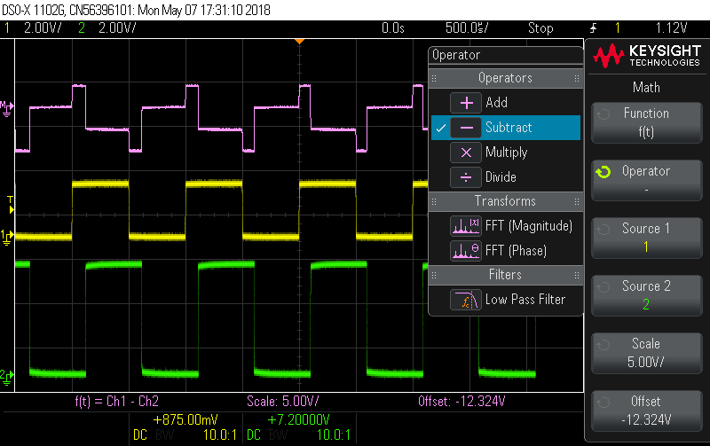
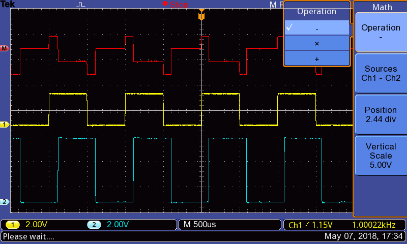
Math functions available with the Keysight DSOX1102G and Tektronix TBS 1202-EDU respectively

FFT

Another clear difference between the two scopes can be seen in the implementation of the FFT. Tektronix has opted to display the signal waveform in a separate window above the FFT waveform or not at all. Keysight on the other hand overlays the FFT over both analog  channels, but still keeps them visible in the background. When selected, Tektronix only displays the waveform being analyzed but, the full waveform is visible. Other than the way in which each scope chooses to display the FFT waveform there is a more tangible difference. Tektronix uses the vertical scale to select the dB per division and the vertical position to move the waveform up and down. The waveform is shifted using the horizontal position knob and the horizontal scale is used to change the frequency per division. You can not really set the span or center frequency of the waveform. Keysight allows for the previously mentioned settings to be set (scale and offset). However, instead of setting the frequency per division and shifting the waveform, Keysight allows you to set the center frequency and the span. This gives more control of the waveform being displayed as well as makes it more intuitive as to what is being displayed.Tektronix provides zoom functionality, what this provides is not quite clear or intuitive. One more thing to note here is the vast difference in number of sample points used to generate the FFTs. Keysight uses 65536 sample points compared with just 2048 from Tektronix. This increase of 32 times allows for a smoother more accurate FFT waveform.

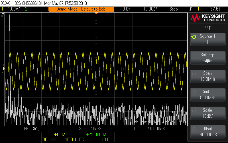
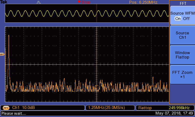
FFT waveforms along with the original waveforms shown on the Keysight DSOX1102G and Tektronix TBS 1202-EDU respectively


Reference Waveforms

While reference waveforms may not be used often, especially by users just learning to use a scope , they are useful. It is even more useful when trying to understand how a waveform changes with different component values. The reference waveforms implementations once again display noticeable differences. Both scopes allow for you to save two reference waveforms locally, and as many as you like via USB. However, Tektronix allows you to display both reference waveforms at the sametime. This is useful to see how a waveform changes with different component values or environmental conditions. Keysight has selected to only provide the ability to display one reference waveform at a time. Keysight does provide other useful features. Because not all reference waveforms line up perfectly, Keysight enables you to both change the scale of the waveform as well as shift it along the time axis. Another nice feature from Keysight is the ability to save math waveforms as a reference waveform. This is helpful again, when debugging analog circuits.

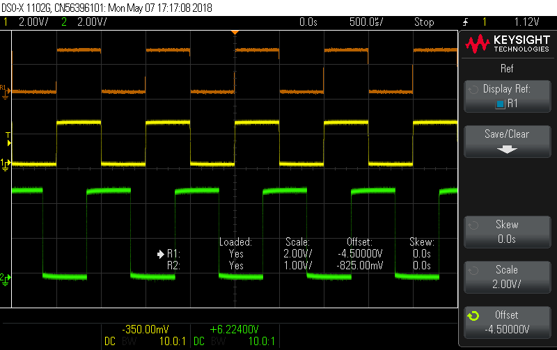
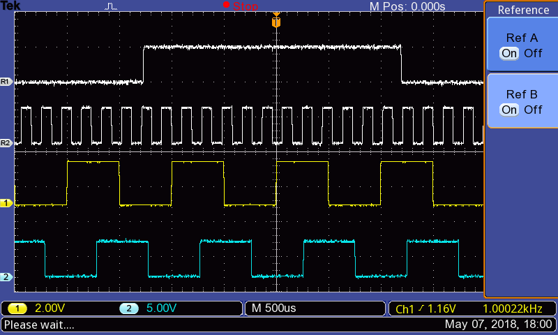
Reference waveforms and functions visible on the Keysight DSOX1102G and Tektronix TBS 1202-EDU respectively


Additional Functions

WaveGen

A useful instrument included as part of the DSOX1102G is a WaveGen. This addition to the scope provides 4 standard waveforms and two other outputs. These include sine, square, ramp and pulse waveforms as well as as well as a DC output between -5V ~ 5V and a noise generator. The waveforms can be set between 100 mHz ~ 10 MHz (except the ramp, upper limit 200 kHz). The amplitudes are adjustable between 2 mVpp ~ 20 Vpp (except sine and noise functions, upper limit 12 Vpp - pulse, noise lower limit is 1 mVpp). The 4 waveforms can also have noise imposed on the signal allowing for such things as noise rejection testing. Besides adding noise to a signal both the sine and ramp functions can be modulated as an AM, FM or FSK signal. The WaveGen does not cover all the functions offered by a conventional function generator, it's not supposed to. The intent is to allow for basic testing of analog circuits by injecting simple waveforms into the system and using an oscilloscope to evaluate the performance.

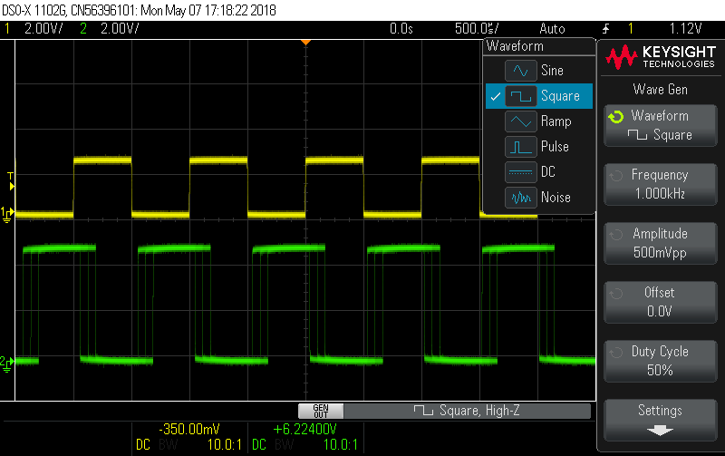
WaveGen waveform menu and setup options

Bus Decoding

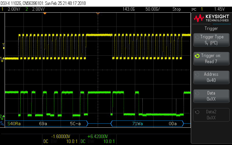
The bus decoding capability is useful for simple digital debugging. With 5 types of serial buses available to decode (CAN, LIN, I2C, SPI and UART), the most commonly used protocols are covered. Each type of protocol has its own setup options. CAN allows for 6 different signal types, various sample points as well as the sample threshold to be set. There are also counters that show total number of received frames, number of errors and the bus load. LIN lets you select either LIN 1.3 or LIN 2.x giving a larger array of signals to be decoded. Unlike CAN there are no counters available for the LIN protocol. Lastly UART/RS232 allows for the number of bits to be between 5 ~ 9 bits, the parity (odd, even, none) , the polarity as well as the order of the bits (MSB/LSB first) to be set. There are other setting that can be changed (HEX, Binary or ASCII decoding) that make the use of the bus decoding a useful tool.

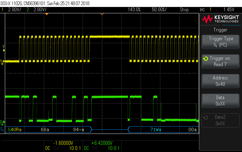
Bus decoding of an I2C signal

In conjunction with each of these bus protocols is the option to trigger on their various parts. This makes finding glitches or errors in messaging simpler. Because the analog waveform displayed just above the digital decoding, if there are any issues the true waveform can be analyzed for defects helping to resolve issues.

Mask Test

Masking allows a user to find infrequently occurring artifacts with minimal effort. Not having a touch screen makes setting up a mask more complex if anything other than the AutoMask feature is used. The AutoMask uses the waveform currently displayed on the display then adds a buffer around the waveform (∓Y & ∓X) ranging from 0V ~ 4V. Statistics are displayed on the screen (number of tests, failing rate, start time duration, etc) giving a more complete picture of testing results.

It is possible to write a mask file that is then uploaded to the scope. Unfortunately the information on how to do this is lacking in its explanation leaving someone wanting to do this guessing what some of the commands are for. It would be useful if Keysight created a PC application that would allow locations to be selected on a virtual display and generate a mask file for you. If a screen shot from the scope could be uploaded to this application it be that much more usable for those trying to use the mask feature.

The test can be run for a set number of tests, a minimum amount of time a minimum sigma or in manual mode. Upon failing a test there are several options that can be selected. The test can be stopped or the screen freezing for immediate evaluation, the waveform can be saved or printed for error logging and lastly a measurement can be taken to quantify the error.

Using automask to find glitches and inconsistencies within a signal

Frequency Response Analysis

A really useful feature and one that fits in with what an oscilloscope is often used for is the frequency response analysis function (FRA). The FRA leverages the analog measurement from the scope as well as signal output from the built in WaveGen. By connecting channel 1 to the input of the device under test (DUT) and channel 2 to the output, the system response can be measured. While this may produce a rough measurement, for an entry level piece of equipment the measurements are acceptable and helpful. This allows those wanting to characterize parts of a circuit or a whole circuit to do so without needing extra equipment.
The settings allow for a wide range circuits to be tested. The available frequency range is 20Hz ~ 20MHz, and the start and stop frequency can be selected anywhere within that range. Lacking is any information on what step sizes are used or how many sample points are used for this analysis. The peak to peak voltage can also be set between 1 mVpp ~ 9 Vpp ensuring no clipping or damage occurs to the DUT.

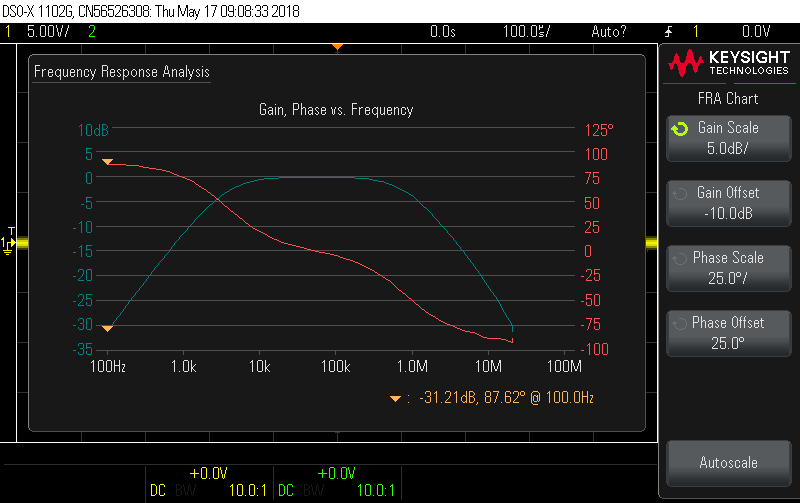
FRA measurement results with a bandpass filter from Keysight

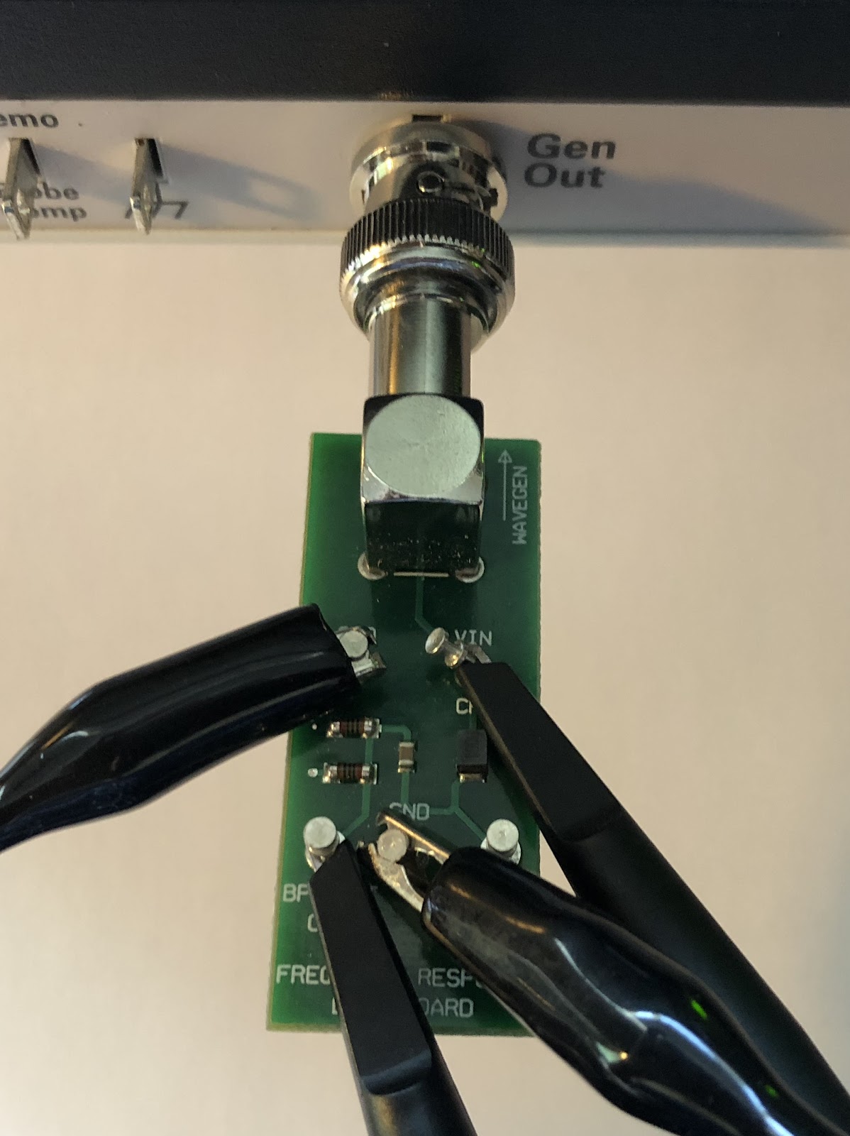
Keysight Bandpass filter board for FRA testing

Conclusion

While this review has covered a lot of the functionality offered by both oscilloscopes not everything was or could be covered. There are some things that may only be useful to a small subset of users or may have minimal impact on the selection of a scope. These things have been left out in this review but may be looked at when these scopes are used in the evaluation of circuits used in future blog posts.

As previously stated, these two oscilloscopes are really not on an even footing, even though they are both entry level scopes. Keysight has clearly put a great deal of effort into their end product. The intuitiveness of the layout and menu settings makes the unit that much easier to use. This is not to say that Tektronix has not provided some nice features, it's more that they have added these at the expense of having an overall great product. Keysight has also added features to make their scope a complete test center for those starting or on a budget. The ability to use test waveforms to see how a circuit responds is very useful. The bus decoding, though not a full logic analyzer, adds some great functionality especially with regards to triggering. In response Tektronix has added courses to their scope or for the non-educational model, trend plots and limit tests. These may help and be somewhat interesting but, limit tests are nothing more than the masking offered by Keysight. Trend plots may be the only differentiator but, alone does not make the scope stand out from others in its class. Added to this is the sluggish response of the Tektronix scope, altering setting should be a simple matter and not a task in of itself. The price point of the two scopes does not help the situation either. Keysight has priced their scope, with all the additions, at half the price of the offering from Tektronix.

Over all Keysight has brought a wonderful offering to the entry level space. When I was looking into this scope I was informed that its core is the same as the higher end DSOX’s but with a lower bandwidth, sampling rate fewer channels and no touch screen. From my experience using this scope and working through each of the functions I would have to agree with such a statement.


Monday, February 12, 2018

TI Motor Drive Bundle (LAUNCHXL-F28027, BOOSTXL-DRV8301) & MotorWare - How Easy is it to Get Your Motor Spinning

Introduction

I would like to thank Element14 and Texas Instruments for selecting me for this roadtest. I applied to review the TI Motor Drive Bundle because of a previous experience with the BOOSTXL-DRV8301 boosterpack and a not so compatible launchpad. I have previously reviewed this boosterpack with less than favourable results. I was therefore hoping that after 3 years of availability, the documentation and support would have improved.

Unboxing & First impressions

Element14 has worked with TI to deliver these boards as complete evaluation kit. The packaging has therefore been altered to reflect this. The three components, each individually packaged, come shipped in a single kit box. The launchpad is packaged in the standard TI box. The DRV8301 on the other hand is shipped in what has been labeled a new product box. If this was a new product, as it may have been during my initial review, this would be acceptable. Its now substanily later in the products life and this generic, oversized box reflects an apathy or disinterest towards this product. The provided motor (DN4240S24-026-TI) is shipped wrapped in bubble wrap. As a perk, a pen with a screwdriver in the back and a level and ruler on the side has been included.
Kit contents as assembled by TI in partnership with Furnell/Newark

The getting started guide for the LAUNCHXL-F28027 has a simple demo to let you know the board is working. The demo interestingly contains two parts. The first demo is done with no PC connected. Once powered up a reference temperature is take. If the temperature changes, the change is reflected on the LEDs to indicate the difference. A new reference value can be set by pressing the S3 switch.
Demo: LEDs displaying change in temperature from initial setpoint

An extension of the first demo is accessed by connecting the LAUNCHXL-F28027 to a PC. After connecting the board, configuring the terminal (115200, 8, No parity, 1 stop) and pressing reset, the board display a text version of the TI symbol.
Terminal after resetting the F28027F

The display prompts you to press the S3 button. This again begins the temperature demo. Instead of only having the LEDs to inform you of the change, the measured value is updated at the bottom of the display.

The DRV8301 doesn't have a quickstart program to run even though there is a quick start guide. Any demo software for this boosterpack is found in the motorware software package and will be look at later in the review.

Getting Started

The various getting started guides all demonstrate how to configure the onboard switches and jumpers before starting. Once these are set there is little help to get you any further.
Proceeding to look through Motorware which had previously installed didn’t help. Knowing that this is an InstaSPIN-FOC board I looked under this section first. Unfortunately there are only projects listed there with no documentation. Attempting to use the Universal GUI to get started revealed the documentation for this software was lacking.

MotorWare labs available for the 8301 Rev B,, notice no documentation listed

Fortunately I was directed by a fellow member of Element14 (najath) to look in the Motorware software for further information. More specifically najath specified to look under the resources section (Resources > Launchpads > F28027F Launchpad). The “Kit Readme First” provides some information but nothing that has not already been provided from the various other getting started guides. The “GUI Quick Start Guide” is also the same as listed under InstaSPIN-FOC. Thankfully najath provided some further instructions. Under “Training:User’s Guides, Labs, Tutorials” is a PDF called “InstaSPIN Projects and Labs User's Guide”. This guide finally gets a user moving forward with this kit.

The resources section has a bit more information but, nothing particularly useful under the F28027F section

After spending a considerable amount of time to get to the kit working it became abundantly clear that TI had not made much, if any progress with this kit since my last review. The main difference between the current and previous review is the help provided from the Element14 community, something I don’t believe I got from TI’s e2e forum on previous attempts.

Documentation

The documentation for this kit has already been mentioned in passing. There is however a decent amount more to be said about this. The quick start guides, of which there seem to be an abundance, don’t point a user in any meaningful direction. The getting started guide for the launchpad shows the user how to configure the board and run the preprogrammed demos. It then points a user to CCS or ControlSUITE for anything further the user may want to do. This may be pretty standard for a getting started guide but, in this case the instructions don't lead to anything concrete to help a user move forward.

Sadly the getting started guide for the DRV8301 is worse then this. After explaining how to setup the hardware, and not really explaining how to connect the motor we arrive at step VI. If anything has been intuitive or well explained until now TI has made sure to rectify that. This last step simply states “Enable your control algorithm and spin that motor”. If this is unclear then TI suggest using MotorWare to get started.

Step 4 listed in the 8301 getting started guide, “Enable your control algorithm and spin that motor”

As has already been outline in the getting started section, this is more complicated than it would appear. There is no clear starting point once MotorWare is opened up. It should be mentioned at the END of the instructions for each project in MotorWare there is one line “Follow the InstaSPIN Projects and User’s Guide to Get Started”.

Atr the END of each project TI lists where to find more information about getting the lab working

This concept of doing things out of order and in a non intuitive manor seems to be common with this kit. The Quick Start Guide for the Universal GUI also lists all the steps needed to run the software including clicking on run. Only after completing the lab, TI explains how to setup the hardware that the software runs on. Just before setting up the hardware but, after the completion of the lab, is the explanation of the GUI’s interface.

Other issues include incorrect referencing/labeling of tables in the lab guide. Steps that are not relevant to some launchpads, including the one included with this kit, are not commented as such. Missing steps, such as those needed to get the Universal GUI working. The steps for the GUI were eventually stumbled upon by reading the readme file in the InstaSPIN_F2802xFUNIVERSAL folder. The GUI has also been changed since the guide for it was last updated in 2015. There have been some components added and others removed. This leaves a user unclear what the functionality of these components are.

Overall TI has really dropped the ball with regards to its documentation for this product. The time between this product first being introduced and now has not been used to streamline the process to get a new user from demo to product. Nore has it been used to increase ease of use. I would be beneficial for TI and it’s customers if these documents where revamped. It would also be helpful if there was one getting started guide with a logical progression to get this kit running with minimum hiccups along the way.

Software

Once the documentation has been worked out and, the single useful starting point found, there is a lot of software to work through. Because of the complexities of the Piccolo along with the those of controlling a motor TI has provided a HAL layer. This allows a user to focus on getting the system working as needed and not worry about setting up registers. Another reason not made clear at first, is the need to hide the code running in the FOC. As this is proprietary and TI not wanting it shared, this HAL also provides access without giving away anything. In order to help the user understand each of the functions are 20+ labs each with multiple parts. While some of these labs are not relevant to the LAUNCHXL-F28027 there are still a large number of demos helping someone working with this kit to understand how to get their project working.

Each lab is provided with complete code that compiles out of the box. Sadly not all the code is well explained and there is a decent amount of following functions to get to the root of their intent. This added effort adds time and complexity to getting through each lab. Along with a unclear explanation of the software in each lab is an equally brief explanation in the lab manual. It is definitely possible to work out the ambiguities but this again adds time. One major issue in this regard is the lack of mentioning when a specific part of the software is not relevant to a microcontroller. Some of the labs require code changes to be made in order to get a better understanding of what the software is doing. The sections in the lab manual are not labeled as not being relevant to different controllers. The only way to infer this is by looking at the #ifdef statements at the top of each section of code.

Another issue with the software and its associated documentation is the assumption of specific knowledge. There are terms and abbreviations used that are not explained or done so very briefly. This would be acceptable if there was some reference information provided to help a new user to learn more, but there are no footnotes or references.

Regarding this specific kit, each project uses a header file to pull in parameters that the user can set for their motor. TI has kindly provided parameters for 16 different motors. This allows for a user to easily switch over to a different motor without needing to figure out the parameters of that motor. TI however forgot or decided to not include the parameters for the motor (DN4240S24-026-TI) that is shipped with this kit. Adding to this issue is the lack of availability of any documentation for this motor. Only after contacting the manufacturer of the motor was I able to get the documentation for it. This one page document still did not provide all the needed information. There is however a page, that was pointed out by another element14 member (MARK2011), that doesn't seem to be anyway linked to the kit or the product identifier that does have the full specs.

DN4240S24-026-TI datasheet as received from the manufacturer

Hardware

The hardware provided in this kit has a few interesting factors. The first and most obvious is the ill fitting nature between the LAUNCHXL-F28027F and the BOOSTXL-DRV8301. The switch S4’s form factor prevents the boosterpack from seating properly on the launchpad.

The S3 switch on the F28027 launchpad can interfere with the DRV8301s ability to be correctly seated

A workaround for this is to provide an extra set of headers to increase the clearance between the bottom of the boosterpack and the switch. The placement of this switch as well as S1 means that any change to these switches requires that the boosterpacks be removed. This again is solved by adding the extension

Headers added to the F28027 launchpad allow the DRV8301 to clear the S3 switch

Another interesting issue noticed is the seemingly incompatibility between the F28027F and the F28027. The previous review I did was supposed to contain an F28027F but instead I received a F28027. Since TI specifies these are pin compatible and the schematics for the LAUNCHXL-F28027/F don’t mention any alterations depending on the provided chips the F28027 was swapped for a F28027F. Unfortunately this did not resolve any issues and the board does not perform like one containing a F28027F.

On the positive side, TI has positioned the BOOSTXL-DRV8301 on top of the LAUNCHXL-F28027F in such a way as to keep S2 and S3 (the two user push buttons) accessible during operation. This allows for those buttons be incorporated into a design without concern for accessibility.

The two user switches have been well placed allowing them to be accessed even when a boosterpack is mounted

SUPPORT

TI included with this kit 6 hours of free online help with your own “personal trainer”. This is probably the one thing TI has done well to move this product forward. The kit includes a card with a TI employees name and email address. Contacting the employee reveals he is someone well acquainted with the software for this kit. I was also informed that should more than the advertised 6 hours be needed that would not be an issue. The help includes anything from just answering a few short questions to getting a walk through on the software. The idea is that after the personal help you should be well on your way with your project. In the few interactions I had through this service I found the employee to be both helpful and courteous.

TI’s e2e forum is still available for this product so if immediate help is needed (the personal trainer is located in Germany) you can try find answers there. The one big difference between the personal trainer and e2e is accountability. By directing your question to one person instead of to a broad forum is there is one person responsible. This leads to both better and more timely responses.

Moving forward

Having spent a decent amount of time getting to know this kit I am looking forward to using it further both as a learning tool as well as in future projects. Something that I have found this kit to be useful for other than motor control is it sability to teach control theory. Because there are so many variables in controlling a motor and both the LAUNCHXL-F28027F and the BOOSTXL-DRV8301 allow for these variables to be controlled this is a great platform for learning applying these control strategies.

I would also like to complete all the labs associated with this kit. As previously mentioned working through each lab and following each function call down to its base call to get a better understanding takes time. I have therefore been unable to complete all 19 labs for the BOOSTXL-DRV8301. Once this has been completed I would like to try implement this kit in a boat project I have been looking at. This would be used control the propulsion propeller allowing for such things as cavitation mitigation to be implemented

Conclusion

Overall this is a quilty kit provided from TI in partnership with Element14. The software and HAL layers are well implemented. There are sufficient demonstrations to allow a user to learn how to use the kit for any application they may have in mind.

Sadly these great qualities are overshadowed by the badly written getting started guide and the abundance of them. Had TI selected to have one getting started guide for the BOOSTXL-DRV8301 that clearly outlined the steps to get the kit working with the demo software this kit would be a lot more useful. Along with this had TI put more effort into the lab manual to explain what the various functions are doing as well as what functions work with what kit that would have helped as well.

I am therefore looking forward to working more with this kit to learn about motor control as well as control theory in general. I am also hoping to implement more motors into my projects now that I have become acquainted with this product and its use cases. For others wanting to learn about motor control and have the time and energy to go through the many pages of documentation and lengthy lines of code, this kit is definitely useful and has a lot to offer.

Original post on Element14 can be found here

Monday, February 5, 2018

MangOH Red and the Legato Framework with Multiple Components


In a previous blog post we took a brief look at the MangOH Red and what makes this new board standout. We then started to explore the Legato framework that runs on the Magoh boards (and the Raspberry Pi, instructions here).

We started off looking at a very simple application, heartbeatRed, one that has only one component, includes one source file and uses one API, to interface with two GPIOs (a button and a LED). In this blog we will move further to an application that has multiple components and various APIs. Since in the “Getting Started Guide” an app called redSensorToCloud is used to capture sensor data and post it to AirVantage, we will look at that app.

System Definition File (SDEF)

In the previous blog we started with the ADEF and explained what that is used for in the overall file system, there is however a file above the ADEF. The SDEF (system definition file) lets the overall Legato framework know what is need when the system is compiled. At this point it should be mentioned, Legato allows you to compile the full framework or compile an individual application to be loaded to the target. The SDEF is always needed to compile the framework. An SDEF can not easily be compared to any one part of a C program. The first section #include makes the file look like a regular C file but, in this case the include links in another SDEF, one used for the WiFi modules.

After the include comes the apps section. This is where the a list of all applications to be included in the compilation of the framework are listed. In the SDEF below there are 7 applications listed to be included in the build. Looking through this section we can see the application we are currently looking at, redSensorToCloud, as well as the heartbeatRed application which we explained in the previous blog post.

If any command line tools are needed when logged in as a root-user through a remote shell we need to make them accessible. In order to do so list them under commands. This works in a command name and command extension pair. The portion on the left hand side of the assignment statement is the name used to call the function from the command line. The portion on the right hand side is the location of the command we would like to make accessible. Once this has been loaded on the MangOH these commands would be accessible when logged in over SSH or through the terminal. It is possible to make an application, local to the MangOH board, executable from the command line in a similar way. The only difference is on the right hand side of the assignment, instead of the commands name (drTool or socialService in the file below) you would list the name of the application to be used.

The interfaceSearch section acts, in away, like a linker file in C. This section shows the compiler where any mksys or other files (.api, .h, etc) files are that may be needed to build the components for the framework. This allows for comments to be truly separated from their interfaces. By allowing interfaces to be stored in one location (not within or part of the component) the same file can be used for multiple components and any upgrades or fixes made would be applied to all components using the relevant interface.

The last section in the SDEF below is that for kernalModules. This shows the compiler where to find prebuilt kernel modules that may be needed or used by some of the components. Each entry in this list points to an MDEF file. The MDEF lists the files used in to build the module as well as passes any other information to the compiler that may be needed to complete these drivers for the target board. Noticeably listed are modules for the sensors on the MangOH Red board, these include the BMI160 and the BMP280.

//--------------------------------------------------------------------------------------------------
// mangOH Red system definition that extends the wifi sdef from Legato.
// Copyright (C) Sierra Wireless Inc.  Use of this work is subject to license.
//--------------------------------------------------------------------------------------------------

#include "$LEGATO_ROOT/modules/WiFi/wifi.sdef"

apps:
{
   $MANGOH_ROOT/apps/GpioExpander/gpioExpanderService/gpioExpanderServiceRed

   $MANGOH_ROOT/apps/MqttClient/mqttClient
   $MANGOH_ROOT/apps/DataRouter/dataRouter
   $MANGOH_ROOT/apps/DataRouter/drTool/drTool
   $MANGOH_ROOT/apps/SocialService/socialService

   $MANGOH_ROOT/apps/RedSensorToCloud/redSensorToCloud

   // The heartbeat app is disabled on mangOH Red because the logging messages
   // from the low power microcontroller make it very difficult to use the console port.
   // $MANGOH_ROOT/apps/Heartbeat/heartbeatRed

   $LEGATO_ROOT/apps/tools/devMode
}

commands:
{
   dr = drTool:/bin/dr
   twitter = socialService:/bin/twitter
}

interfaceSearch:
{
   $MANGOH_ROOT/apps/MqttClient
   $MANGOH_ROOT/apps/DataRouter
   $MANGOH_ROOT/apps/MuxControl
   $MANGOH_ROOT/apps/SocialService/interfaces
}

kernelModules:
{
   $MANGOH_ROOT/linux_kernel_modules/mangoh/9-mangoh_red_dv4

   // Required for bmp280 & bmi160
   $MANGOH_ROOT/linux_kernel_modules/iio/0-iio
   $MANGOH_ROOT/linux_kernel_modules/iio/1-iio-kfifo-buf

   // Required for bmi160
   $MANGOH_ROOT/linux_kernel_modules/iio/2-iio-triggered-buffer

   $MANGOH_ROOT/linux_kernel_modules/bmp280/2-bmp280
   $MANGOH_ROOT/linux_kernel_modules/bmp280/3-bmp280-i2c

   // Used on mangOH Red DV3 and later
   $MANGOH_ROOT/linux_kernel_modules/bmi160/3-bmi160
   $MANGOH_ROOT/linux_kernel_modules/bmi160/4-bmi160-i2c

   // spisvc creates a spidev device which will appear as /dev/spidev0.0 once the spidev module is
   // loaded.
   $LEGATO_ROOT/drivers/spisvc/spisvc
}

While the SDEF may not be something you interact with very often it is still an important file to understand. Drivers may need to be added or altered and you may want to run applications that are not standard or remove some that are.

Application Definition File (ADEF)

The next file that is used in the compilation of a system/application is the ADEF, this is the first file that is always needed. The ADEF lists the executables to be run within this application and what components are needed for that executable. Any resources that are specified in the ADEF are also given a handle by which they can be referenced

While all ADEFs have the same basic blocks and we have previously looked at the ADEF, what's in them can differ and appear complicated. The ADEF below starts off the same as in the previous blog post with sandboxed, start and version all set the same. The first and most noticeable difference comes under executables. In this section, instead of a one to one mapping, the executable redSensorToCloud is mapped to two components. In the ADEF below the executable redSensorToCloud is mapped to two components. This means that when redSensorToCloud is executable both components (avPublisherComponent and sensorsComponent) are run and both of their COMPONENT_INIT functions are run at startup.

The next block, processes, has previously been looked at. Subsections run and envVars tell the application which executables to run as well as what environment variables are accessible from within the application. The last section bindings in this ADEF are slightly different than those previously encountered. While the section provides the same functionality, the API in this file behaves slightly differently than those found in the previous application. The previous API provided a handle to directly manipulate the internal interface. This application’s API does not provide such functionality. The first API, le_adc, connects directly to the interface, by specifying the ADC channel in the function calls the API knows what channel to read from (the exact code can be seen here and here). The second API avdata is used to send/receive data between the MangOH board and the AirVantage server. This API requires that a record object be created. Data is inserted into the record, the record is then pushed to the server. Therefore because these two APIs use objects, there is no variable name to be used in the CDEF or source files.

sandboxed: true
start: manual
version: 0.1

executables:
{
   redSensorToCloud = ( avPublisherComponent sensorsComponent)
}

processes:
{
   run:
   {
       ( redSensorToCloud )
   }

   envVars:
   
       LE_LOG_LEVEL = DEBUG
   }
}

bindings:
{
   redSensorToCloud.sensorsComponent.le_adc -> modemService.le_adc
   redSensorToCloud.avPublisherComponent.le_avdata -> avcService.le_avdata
}


Component Definition File (CDEF)

In order to increase reusability, this application has been written using two CDEFs. This allows for the various components to be used in multiple applications without needing to rewrite code.

Individually the CDEFs are not complex and are even similar to those previously discussed. There are however, some noticeable differences. In the avPublisherComponent, there is a previously unseen subsection. The component subsection informs the compiler there is some functionality in the sensorsComponent needed by the current component. This other component is therefore required by the current component, similarly this included component or any subsequent components have required components those too will be imported. This also implies codependence is not allowed, if this does occur the application will not compile. When done correctly, the dependant components COMPONENT_INIT will be run after the non-dependant component’s has run. Other than the component section there is the previously seen api section which lets the component have access to the avdata_le API. There is also the sources section which list the C sources file needed to build this component.


cflags:
{
   -std=c99
   -I${CURDIR}/../sensorsComponent
}

requires:
{
   api:
   {
       airVantage/le_avdata.api
   }

   component:
   {
       sensorsComponent
   }
}

sources:
{
   avPublisher.c
}
avPublisherComponent…

Other than the longer list of source files listed in the sensorsComponet CDEF the noticeable difference here is the file subsection. This section allows us to provide files (as defined by linux) to the application that are not part of but, are needed by the application. It also tells the application where to find the specified file within the application sandbox. These files need to be accessible at run time and not build time as that is when the application will look for them.


cflags:
{
   -std=c99
}

requires:
{
   api:
   {
       le_adc.api
   }

   file:
   {
       /sys/devices/i2c-0/0-0068/iio:deice0/in_accel_x_raw    /sys/devices/i2c-0/0-0068/iio:device0/
       /sys/devices/i2c-0/0-0068/iio:deice0/in_accel_y_raw    /sys/devices/i2c-0/0-0068/iio:device0/
       /sys/devices/i2c-0/0-0068/iio:deice0/in_accel_z_raw    /sys/devices/i2c-0/0-0068/iio:device0/
       /sys/devices/i2c-0/0-0068/iio:device0/in_accel_scale    /sys/devices/i2c-0/0-0068/iio:device0/
       /sys/devices/i2c-0/0-0068/iio:deice0/in_anglvel_x_raw  /sys/devices/i2c-0/0-0068/iio:device0/
       /sys/devices/i2c-0/0-0068/iio:deice0/in_anglvel_y_raw  /sys/devices/i2c-0/0-0068/iio:device0/
       /sys/devices/i2c-0/0-0068/iio:deice0/in_anglvel_z_raw  /sys/devices/i2c-0/0-0068/iio:device0/
       /sys/devices/i2c-0/0-0068/iio:device0/in_anglvel_scale  /sys/devices/i2c-0/0-0068/iio:device0/
       /sys/devices/i2c-0/0-0076/iio:device1/in_temp_input     /sys/devices/i2c-0/0-0076/iio:device1/
       /sys/devices/i2c-0/0-0076/iio:deice1/in_pressure_input /sys/devices/i2c-0/0-0076/iio:device1/
   }
}

sources:
{
   init.c
   sensorUtils.c
   lightSensor.c
   pressureSensor.c
   accelerometer.c
}
sensorsComponent…


Over all the file system started with the SDEF at the very top and is followed by the ADEF and CDEF respectively below it. Each CDEF will list the source files as well as any other system requirements it needs to build the component. Below and in away to the side of the SDEF is also the MDEF, these list/build the modules needed by the kernel. In this application MDEFs for the various onboard sensors are included and can be thought of as drivers. A full outline of this application (without the MDEFs is provided in the image below).

2017-10-18 10_01_25-MangOH File Structure using Legato - Multiple Components.pdf.png


The next step is to build our own application, this will be looked at in future blogs. The first project will be to attempt to use a Raspberry Pi shield to measure temperature, humidity and air pressure. Once this has been accomplished a future project will look to incorporate sensor readings along with GPS data. This project's goal will be to attempt to use the MangOH Red as a standalone Weather Balloon board, with the cellular modem providing communications and the on chip GPS providing location. Sensor data will be collected via external sensors but will be relayed in semi realtime back to AirVantage via cellular networks.