Introduction
I would like to thank Element14 and Rohm Semiconductor for giving me this opportunity to review and give feedback on the Rohm SensorShield-EVK-003. The SesnorShield is Rohm’s ecosystem to allow engineers and designers to quickly and easily assess their sensors. With so many sensor options today, the ability to quickly test and evaluate a new sensor is helpful. Rohm has chosen to go with the Arduino ecosystem as the backbone of their evaluation ecosystem rather than try force testers to use Rohm’s own microcontrollers from LAPIS.
Out of the box / unboxing
The kits is packaging presents the contents well to the user. Upon opening the box there is a well labeled pamphlet explaining the basics of the kit. This information includes what sensors are included, where each one should be connected (what interconnect each uses) and what voltages should be set for each. Once this is removed along with the protective foam the sensors are visible
each in separate containers along with the SensorShield in an opaque antistatic bag.
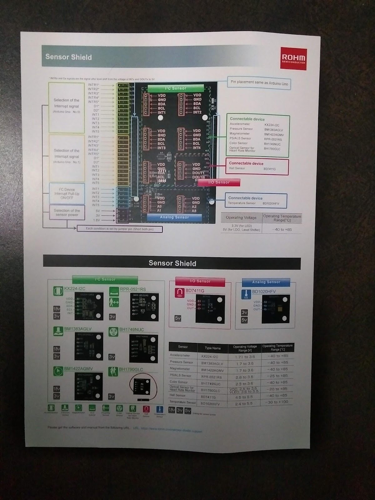

There are 8 different sensors included in the kit. These sensors target a wide array of applications and markets and don’t necessarily have any relation to each other. The included sensors are:
Each of these sensors are mounted on a small PCB that resembles a tile. These tiles are made to interface with a motherboard or SensorShield also included in the kit. This SensorShield makes interfacing the various tiles with any Arduino Uno compliant interface seamless.
Documentation / Datasheets
While the kit does come with an outline, there is no getting started guide included with the kit or well displayed starting point. The only information to get started is in the form of a URL in small font at the bottom of the included pamphlet. This URL is either in English or Japanese depending on which side of the pamphlet is being used. Although it would be expected the the information provided on both to be the same this is not the case. There appears to be some clearer diagrams on the Japanese home page.
After visiting the product home page and selecting the sensor you wish to begin with there are clear instructions provided to get it working correctly. Each sensor page is well laid out and provides various pieces of information. First is a link to the sensors datasheet followed by a JPG of both the circuit diagram and PCB layout.

Below this is an image of the SensorShield board and what section of the shield the sensor should be connected to. Also in this image is how the power jumber should be set to insure the correct voltage is selected. The next to sections are what make using this kit so easy. The Manual section provides a clear yet concise step by step instruction to get the the demo software working. Included here are steps for connecting the sensor tile, setting the voltage, selecting the correct software demo and how to run it. Lastly there is an explanation of the passive components on the PCB. The last section provides the Arduino libraries and demo to test the sensors.

Overall this style is well laid out and follows a nice progression. This progression allows a user to first be familiar with the sensor, how it should be connected and finlay how to use the demo. The use of the same flow for all sensors enables a user to easily move from one sensor to the next.
The one improvement Rohm could provide would be to change the format used for the schematics. While the use of PDFs is sufficient for the board layout this is not so with the schematics. The nature of JPGs is to soften edges which makes zooming in on labels impossible. There is a PDF version of the schematics (discovered by Jan Cumps) however upon further investigation it can be seen that this PDF has a different version number. Therefore there are some minor labeling differences between the PDF and JPG versions..
First impressions and Setup
Following the manuals found on each of sensor pages gets the kit working quickly even for the uninitiated user. The ability to have a sensor reporting data in under 5 minutes is definitely possible if the instructions are followed.
Each sensor manual includes a screenshot of what data should be visible on the output terminal (data is sent via UART to a PC terminal). While often this can change with each revision, this is not so with Rohm's manual. Every screenshot provided was the same as the softwares actual output. This added confirmation provides the user with that much extra confidence in the software and hardware.
It should also be mentioned,to aid in the ability to use multiple sensors together, the I2C pull-up resistors have not been populated on the individual sensor tiles. instead the 1k pull-up resistors have been added to SCL and SDA lines on the SesnsorShield. This prevents multiple parallel resistors decreasing the overall pull-up resistor value. There are solder pads available for resistors to be added on each tile should they want to be used as stand alone.
Sensor Performance
The overall ecosystem allows for easy evaluation of each sensor and while the setup is well done, the performance of each sensor is independent from the test ecosystem. While each sensor was tested for ease of setup and use, performance was not the main focus. Some sensers did go through more performance testing and that information will be included in the sensor summary below.
BD1020HFV - Temperature sensor
The BD1020HFV is an analog temperature sensor with a sensing rage of -30℃ ~ 100℃ and a listed accuracy of ±1.5℃. The BD1020HFV has a linear response of -8.2mV/℃. Since the BD1020HFV is analog its overall accuracy depends greatly on the ADC used with it. Unfortunately the Arduino Uno’s ADC is only 10 bits wide and while this should provide a resolution of 0.13℃ this does not seem to be the case. In the graph below it can be seen that the BD1020HFV in conjunction with the Arduino has a resolution of 0.6℃.

This can also be seen in the seemingly less responsive parts of the graph. Although it may look like the BD1020HFV can’t detect the temperature changes that the other 4 sensors do this is only because there needs to be a full 0.6℃ of temperature change before that value is fully reflected on the graph.
What can be seen from the graph is the variability of the output from the BD1020HFV. This is partly due to this fluctuation along with the resolution of the ADC among other factors. Also noticeable is the uncalibrated value is ~4℃ above those of the other temperature sensors.
BM1383AGLV - Pressure sensor
Still with environmental sensors is the BM1383AGLV digital pressure sensor. The BM1383AGLV uses the piezoresistive effect to detect changes in outside pressure, this signal is then put through what is assumed to be a 22 or 24 bit ADC. The return value via I2C is therefore a 22 bit value that the datasheets appears to suggest should be divided by 2048. Both of these pieces of information are unclear from either of the datasheet or the provided Arduino code. This is unfortunate as it leaves the user unclear exactly how to interpret the data from the BM1383AGLV.
The sensor in conjunction with the Arduino code appears to output data consistent with the actual forecasted data. In a direct comparison with BMP180 from Bosch the readings between the two followed the same progression albeit with a clear offset between the two.
BM1422AGMV - Magnetometer
The next sensor is used for navigation among many other possible applications. The BM1422AGMV is a triaxis magnetometer with measurment rage of ±1200µT. The stated sensitivity of 0.042µT is great enough to detect fluctuations of the current in a wire.
With an operating current of 0.15mA the induced magnetic field is approximately 60µG ~ 3µG or 0.006µT ~ 0.03µT wich can be enough to detect fluctuations in the PCB traces close to the sensor. This however, does not seem to have been taken into account with the design of the tile and instead the BM1422AGMV is placed in the center of all the components.
Even with this layout and sensor sensitivity, the overall performance is good. Running a short static repeatability test it can be seen that the variation (noise) is less than ±0.5µT or approximately 100 times less than the magnetic field strength of the earth on all three axis.


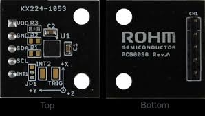
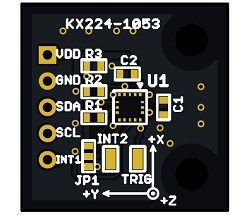
KX224-I2C - Accelerometer from subsidiary Kionix
The next sensor is the KX224-I2C. Kionix was purchased by Rohm in 2009 and is now a subsidiary of Rohm. The KX224-I2C can be used to detect forces up to 32g but has settings for both 8g and 16g. With a lot of functionality built in, this sensor can be used to detect forces as well as device orientation without needing to do any complex calculations.
The Arduino demo for this sensor outputs the measured X, Y and Z axis values. Unfortunately the code is not explicit as to what range is being used. Looking through the API and library code, it can be seen that there is no selection possible and 8g is the sensitivity range used.
The KX224-I2C datasheet explains that the accelerometer is trimmed at the factory removing the need for any calibration later on. These correction values are stored in nonvolatile memory and are applied to the sensor at power up. This is helpful but as can be seen in the images below, neither the X axis or the Y axis are well calibrated. In order to get a reading of zero gs on both the X and Y axis, considerable correction was needed in both planes.

Further to this is the Z axis calibration. In order to have a 1g reading on the Z axis the sensor needs to be manipulated in a completely different direction than what is needed to achieve a zero reading on the X and Y axis. This leads to the question of how the sensor is calibrated and in what plane. Without the ability to get a 0, 0, 1 reading it is unclear how the sensor was calibrated.
Even with these inconveniences and inaccuracies, the demo is very beneficial to understanding the basic functionality of the senor. In order to explore the other functions such as tilt, freefall and single/double tap detection custom code would need to be written. This is because Kionix has chosen not to implement any library functions to demonstrate these functions.
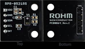
RPR-0521RS - PS/ALS (Proximity/Ambient Light) sensor
Staying with sensors that are often used for personal electronics is the RPR-0521RS. This is a proximity and ambient light sensor in the same package. The proximity sensor uses the reflection from an internal IR LED to determine how far an object is. While this reflection does depend on the color and material reflecting, the datasheet does outline the test procedure used for internal testing. The code for this demo outputs a count as well “Near” or “Far” depending on that number. Looking through both the datasheet and code, there is no clear explanation for this output value from the sensor.
With no easy way to test or evaluate the ambient light sensor other than to use a constant light source (LED) and perform a static that is all that was performed. During an extended test of more than 2 minutes the lux value didn’t change. While this does not give feedback on the accuracy of the measurement it does provide confidence on the sensors consistency and repeatability.
BH1790GLC - Optical heart rate sensor
The BH1790GLC is a optical heart rate sensor with an internal ADC and output over I2C.
Having an internal ADC enables the BH1790GLC to output a value instead of an analog signal, like those used in hospital grade equipment do. This allows for simplified circuitry and interfacing with microcontrollers when building products.
Having an internal ADC enables the BH1790GLC to output a value instead of an analog signal, like those used in hospital grade equipment do. This allows for simplified circuitry and interfacing with microcontrollers when building products.
Unlike all the other sensors in the kits the BH1790GLC has two demo programs. These demos show the results from the sensor in different formats. The first program graphes the outputs of the measured values. Although these values may appear arbitrary, the demo gives a good indication how the sensor works as well a showing that he sensor can clearly detect a pulse.

The second demo looks for the sensor to be covered before activating the green LEDs.This status is indicated by the second value in the output (Wearing). The demo them proceeds to output the beats per minute as well as the “Wearing” status.
Using the second demo the heart rate of several people were measured using three methods. The first was using the BH1790GLC. The second method was using a Fitbit Versa. The last method was mauly counting beats for either 15, 30 or 60 seconds. In all cases there was minor variations between the BH1790GLC and the other two methods. This would lead one to believe that even the relatively simple Arduino demo is reliable enough non-heath critical consumer products.
Both demo programs demonstrate very well the abilities and ease of use of this sensor. The one major drawback to these demos are how easy they are to stall. That is, how easy it is to cause the program to hang or sensor to stop working. This happens when a finger or other body part touches the SDA and SCL pins. Why this causes the demo to stop is unclear but putting tape over these pins resolves the issue.
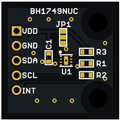
BH1749NUC - RGB color sensor
The last I2C sensor in the kit is the BH1749NUC - RGB color sensor. The output of this sensor like the heart rate and PS/ALS is an unquantified value. Using a laptop screen and Microsoft Paint the three primary colors were used to test the sensor. This is by no means a definitive test as the wavelengths of the colors displayed by the screen are unknown. It's also unclear how much effect the brightness of the screen affects the output.
The tables below show the readings from the sensor at distances of 1” and 0.5” away. The first column in each pair is the RGB value and the second column is measured values. In both tests the sensor was enclosed in a small box to prevent outside light from affecting the measurements. The first thing noticed from this test is the effect the distance between the sensor and the source has even in an enclosed box. The second point noticed, even without extensive testing, is that there is a correlation in the output value and the RGB setting. Although the correlation is not very obvious, with more data points it is believed a clearer correlation could be established.
1" Distance setting
| ||||||||||||||
R
|
100
|
5
|
255
|
35
|
255
|
39
|
255
|
55
|
0
|
1
|
0
|
5
|
0
|
5
|
G
|
0
|
2
|
0
|
9
|
255
|
88
|
0
|
46
|
0
|
39
|
255
|
113
|
255
|
76
|
B
|
0
|
3
|
0
|
4
|
0
|
16
|
255
|
64
|
255
|
61
|
255
|
70
|
0
|
14
|
0.5 " Distance setting
| ||||||||||||||
R
|
100
|
11
|
255
|
64
|
255
|
73
|
255
|
67
|
0
|
3
|
0
|
11
|
0
|
10
|
G
|
0
|
12
|
0
|
21
|
255
|
176
|
0
|
94
|
0
|
83
|
255
|
237
|
255
|
165
|
B
|
0
|
8
|
0
|
11
|
0
|
35
|
255
|
132
|
255
|
128
|
255
|
151
|
0
|
31
|
While this should be a relatively easy sensor to use, the datasheet in not clear on a number of points. The first is how intensity affects the sensors measurements. With no information it is unclear as to what affect brightness has on the sensors measurements. Next is a total lack of any information as to what the measurement values mean or what the maximum value from the sensor is. Lastly is any information regarding a register and measurement value called Green2. Without this information the BH1749NUC is an interesting sensor that can only be used in calibrated environments.
One design consideration that Rohm has taken into account in the possibility to use multiple sensors together. Although other sensors have the ability to change the I2C address they do not provide for this on the evaluation boards. Rohm has taken the steps to allow the user to choose either the default address or by adding a pulldown resistor a secondary address.
BD7411G - Hall sensor
The last sensor in the evaluation kit is the BD7411G. This is a omnipolar hall sensor meaning polarity is not detected, only magnetic field strength. Of all the sensors in the evaluation kit this is the simplest and easiest to use. The only test that can be done with this sensor is a repeatability test. But even this test, unless the magnet is moved on the exact same path, can produce varying results.
This senor was therefore not tested other than to see how the software performs. Being a simple on/off output the code is basic and easy to follow. Unsurprisingly the demo works well and is easy to understand.
The one major setback for this sensor is that in its datasheet it is grouped with 1o other sensors. While most of them operate similarly the BD7411G seems to be singled out the most times. This makes for doing quick checks on some aspects more difficult because you are not always sure the information is relevant to the sensor on hand or not.
Software Provided Code Examples / Libraries
Each sensor is accompanied by an API and an Arduino demo. This demo should be able to be run from most boards that conform to the Arduino Uno Connector pinout. Throughout this review with an Arduino Uno R3 as well as an IoT202 from Siemens were used. The demo software and associated libraries provided with the sensors allow the used to quickly test the sensors and see how they work. Each library provides only the most basic funcilality out of the box. This would not only apply to the previously mentioned KX224-I2Cbut to all the I2C sensors that allow for any setup and configuration.
Positives
The SensorShield-EVK-003 is by far one of the simplest evaluation ecosystems to get moving with. The progression presented for each sensor helps a user move seamlessly through getting a sensor up and running. This combined with the consistency across all sensors means that once a user has figured out this progression with one senor they can readily apply it to other sensors.
Rohm’s idea to keep each demo simple means understanding the code as well as the functionality is easy even for the new user. Except for the heart rate sensor demo each demo is made up of basic commands that often employ nothing more than a read or write to or from a pin or port. The data received from the sensor is then displayed in the simplest yet most help manner possible. Over all Rohm has made the process as useful as possible while still keeping the demos easy to follow.
Concerns
There are few few drawbacks to how Rohm has presented the information and most of the issues are not with the demo but more to do with the datasheets. In a number of the datasheets information was lacking. This lack of information ranged from no explanation for data registers to no information regarding what the output values mean. There was also grammatical errors in the datasheets that made understanding some of what was trying to be conveyed harder to understand.
Further to this is no comments with in the software demos. Even though the code is simple, some further explanations would help in cases where the intent or action is unclear. This is most notable with the KX224-I2C where the sensing range selection is unclear.
Another communication issue is regarding the routing of interrupts. With only JPG schematics easily available and the inability to read all the labels it's unclear how some of the interrupts are routed. This leads to some issues when trying to use some of the demos that use interrupts.
Lastly there are two issues with regards to labeling. On the silkscreen of the analog sensor (BD1020HFV) there is some confusing markings. While the SensorShield uses markings A1, through A4 they do not match up to those on the Arduino board. A1 from the SensorShield connects to A0 on the Arduino. This adds some confusion to troubleshooting as well as following the routing of signal on the board.
The other labeling issue is with the color sensor. In order to allow for changes in the I2C address, the PCB has extra three pads. These pads allow for the address pin to be connected to either VCc or GND. However in the JPG of the board this connection seems to be missing or is very hard to see. This has lead some users to assume that there may not be a connection there.
Conclusion
In conclusion, the SensorShield-EVK-003 is well designed and has a lot to offer in the way of user experience. The ability to have the sensors outputting usable data in under 5 minutes is useful and impressive. The consistency between each sensor tile as well as how the information is presented is another great achievement from Rohm. While there are some drawbacks mentioned overall for testing sensors this kit does deliver an overall good experience. With just a few changes Rohm could make that experience even better but with what has been delivered I would not complain.
No comments:
Post a Comment