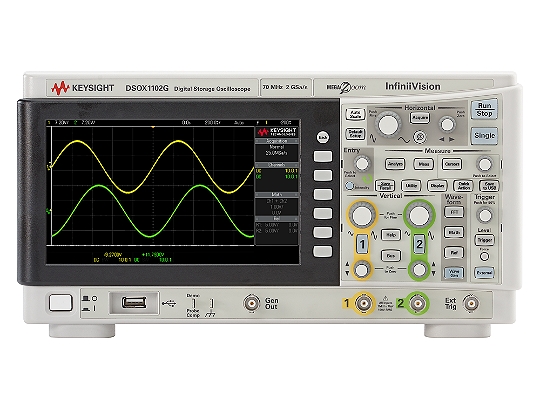
I recently received a new oscilloscope, the Keysight DSO1102G, for my workbench. I’ve had the Tektronix TBS1202B-EDU on my desk for a long while. Having never read through its manual I thought now would be a good time do a thorough read of both manuals. This would give me a better and more complete understanding of these two oscilloscopes. It would also allow me to have a greater appreciation of the differences between the two oscilloscopes without missing anything.
Out of the box these two oscilloscopes are truly an unfair comparison. Tektronix’s offering is an oscilloscopes and nothing more. While it does allow for courses to be uploaded to the unit, it is still just an oscilloscope. Keysights offering has multiple instruments built in. These include, serial bus decoding, wave generator and frequency response analyzer. The only reason to compare them is how their respective companies market them, they are both offered as entry level instruments. It will therefore be with this in mind that we will review these two instruments.
Documentation
Since both are packaged pretty much the same, the review will start with the documentation. Tektronix has taken the approach, this is for beginners and have written their user manual as such. The first ~70 pages, out ~170, explain how to use the instrument in a detail, that includes use cases and how certain measurements should be made. While helpful, this makes the likeliness of someone taking the time to fully familiarize themselves with the instrument less likely. On the other hand Keysight has chosen to just explain what functionality is included and how to access it. When needed, further explanation is provided. This minimalist approach along with the scopes built in help, makes the ~90 pages of the user manual that much easier to read. Keysight’s approach includes placing the information where you need it most, on the scope itself. This information is accessed by holding down the function key in question for a few seconds.
Unfortunately even with this well intending approach and built in help there are some functions that could use a clearer and slightly more in depth explanation. This includes the math function’s two functions (f(t), g(t)) and what the differences are between them. The notes on FFT functionality do not explain how to set the resolution and span. Masking is probably the best example of missing or shorthanded information. A diagram along with the code segment and an explanation tying the two together would have made this section more useful. One other missing piece of information noticed is how to use the trigger setup RxY:Data, TxY:Data and if this is even possible ([Trigger] > Trigger Type > Trigger Setup > Trigger Rx Start, when [Bus] > Mode = UART/RS232).
From this perspective the manual from Tektronix is some what better as every function is discussed in greater detail and explains clearly how to get each function to work. It should however be noted that in both manuals there was some functionality that either did not work as described or was not accessible.
Front Panel
At first glance the front panel of both units have a similar appearance with the Keysight having a slightly cozier feel compared to that of Tektronix. This likeness is quickly dismissed after spending time using the oscilloscopes. The cozy feel felt with the Keysight is due to the 42 buttons and knobs (51 functions) compared with the 35 (38 functions) on the Tektronix. The additional 7 function buttons allow for quicker and more intuitive access. These include a display button that allows such things as persistence to be quickly accessed during debugging sessions. A dedicated knob for cursor control allowing you to quickly take measurements of the the waveform being analyzed. There are also buttons for the added functionality (WaveGen, Bus and External Trigger) but, this applies to both instruments as the Tektronix has “course” and “function” buttons to access course material and the frequency counter. One really nice addition on the Keysight is the back button. This allows you to move seamlessly through menus without needing to go back to the top every time you want to go up one level.
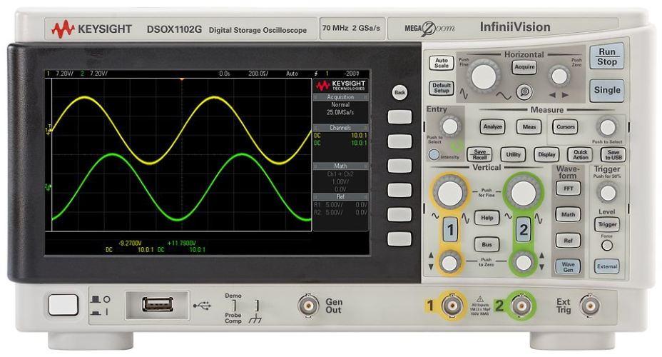
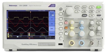
Keysight DSOX1102G next to the Tektronix TBS1202B-EDU
Display
Turning on the instruments brings the 7” displays to life. There is a noticeable difference between the two displays. Keysight’s is both sharp and clear with a nice update rate that makes visualizing waveforms a simple matter. While Tektronix’s display is not particularly hard to see or poor, there is definitely noticeable twitching in the displayed waveforms. Whether this is due to a slow update rate or because the internal processor can't keep up is unclear. You’ll also notice that even though both have 7” of real estate, Keysight reserves approximately an inch for information such as sample rate, probe attenuation, math equation and reference waveform information. While this does allow for the full waveform to be visible even with the information displayed it does change the screen size from 7” to a more realistic 6”. Tektronix, on the other hand overlays this information on the side hiding part of the waveform while this information is visible. Other noticeable differences are with the lighting. Keysight’s display settings work more like a phosphorus oscilloscope where the intensity only affects the waveform. The intensity of the grid lines are set separately. Tektronix however has decided to tie all of these together and only have one setting “backlight”. This doesn't allow for any “tuning” of the waveform like on older phosphorus scopes or to alter the contrast between various parts of the display.
Analog Input
The main function of any oscilloscope is its ability to display input waveforms accurately and reliably. With the advertised specifications of the Tektronix oscilloscope surpassing that of the Keysight’s I was sure that Tektronix would outperform Keysight. In order to test the analog functionality, the test signals from each scope were used. Since the test signals are derived from the scopes internal clock this should be an acceptable waveform to test each scopes functionality as well as how well each function works. Unfortunately this quickly revealed differences between the abilities of the two scopes. Tektronix’s ability to keep up with the sample waveform was noticeably labourd. The inability to clearly sweep the signal made it obvious there is some memory or processing limitations preventing a clear waveform from being displayed. Another issue noticed, increasing the time base can introduce aliasing. The square wave with a measured period of 1ms using a time base of 50 ms/div, measured 100 ms using a time base of 250 ms/div. On the other hand the Keysight had no issues with either of these two scenarios. Keysight shows the waveform as a blur at the larger timebase, which at this time base it is. Zooming in on the waveform, the period measures 990 µs compared to the previous 992 µs. For someone familiar with the Tektronix scope, these issues may not be a big problem. Since these scopes are aimed at beginners and students, this can conceivably lead to incorrect measurements and a lack of understanding of the concept being taught.
A feature often used to prevent issues such as these is autoset. It should be noted, both Keysight and Tektronix depart from the documentation with regards to this function. Auto scale/set on the two scopes favors different setup parameters. Regardless of what is stated, if there is a valid signal on both channels, Keysight always favours setting up the scope using channel 1 and Tektronix channel 2. Tektronix has taken the autoset one step further than just stabilizing the waveform on the display. A quick press of the autoset button brings up a menu if the waveform being sampled is recognizable. A square wave, for example, gives you the option to see multiple periods, a single period or just the rising/falling edge. If, however, you hold the key down for an extended period, a new menu is displayed. This menu allows you to turn on/off autoranging as well as to select if you want just one or both the vertical and horizontal axis to be auto scaled.
Trigger
An important function of any scope is the trigger. Allowing the user to “freeze” the waveform when just the right portion comes past is what makes a scope useful. However, not all triggers are created equal. Keysight offers 7 triggering options compared to 3 from Tektronix. Offered by both scopes are; edge triggering (rising, falling and alternating/either), pulse width and video (NSTC, PAL and SECAM). Keysight added to this list, pattern matching, rise/fall time, setup and hold and triggering on serial events. Pattern matching allows you to specify a digital value each of the three channels (1, 2 and External) should have to initiate an event. The rise/fall time allows you to specify the time that a signal either rises from 10% - 90% or falls between these values. Triggering on a serial event allows for specific packets to be used as triggers. Also with a range of serial protocols implemented (CAN, I2C, LIN, SPI or UART/RS232) this feature has a lot of potential to resolve issues quickly.
Because not all signals are clean, both companies offer various pre-filters that can be applied to the input signal. These filters include noise rejection, HF rejection and LF rejection, to clean up the signal and improve triggering. Tektronix only allows for one filter to be used at a time. Keysight on the other hand allows for the stacking of these filters (in what order they are applied is unclear). Unfortunately with Keysight it's not clear what the signal you are triggering on looks like. This is because there is no way to easily view the signal being fed to the trigger circuit. Tektronix provides this ability by holding the trigger button for longer than 5 seconds. While not a major issue, it's helpful to know if the filters being applied are helping or potentially hurting your trigger acquisition.
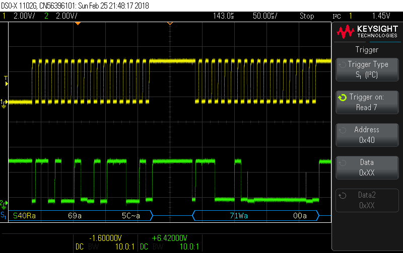
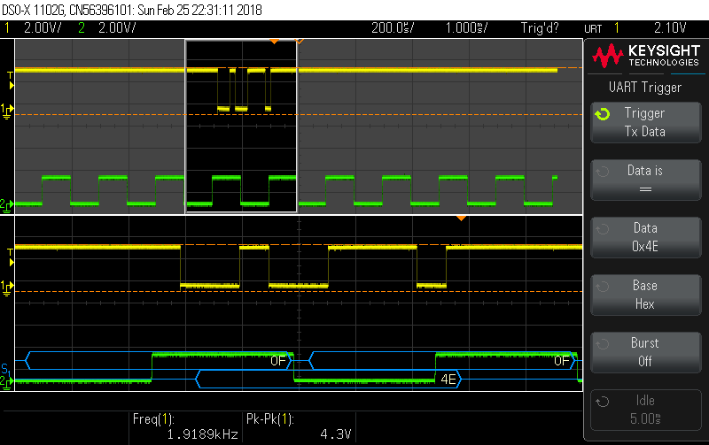
Keysight DSOX1102G triggering on I2C and UART signals respectively
Waveform Zoom
The zoom function offered by Keysight and Tektronix allows a user to examine parts of the waveform in greater detail. Implementations between the companies shows a varying focus on how they perceive their customers using this function. Keysight locks the waveform’s scale and horizontal position in place. The horizontal scale and position knobs are then used to zoom in/out on the waveform and shift the area of zoom respectively. Tektronix assumes the user may not just want to shift the waveform and zoom, but may want to change the time base or shift the trigger time value. For this reason Tektronix has kept the original functionality assigned to the horizontal controls. In order to zoom or to shift the magnified area, the multipurpose knob is used. Pressing in on the knob switches between altering the scale and the position of the zoom area.
This becomes more noticeable when you attempt to take measurements or change other settings while in zoom mode. Keysight keeps the cursors accessible (you still use the cursor knob) as well as all other functions such as math, FFT and Reference Waveforms. Although Tektronix does provide access to the math and reference waveforms (FFT terminates the magnified view) the math waveform is displayed but the reference waveforms are not. It would therefore appear Tektronix assumes the user is just interested in getting a closer look at the waveform. Keysight on the other hand assumes the user may want to do more while zoomed in. This includes taking more precise measurements with the coursers, compare sections of the waveform to a reference waveform or even look in detail at parts of the FFT, all of which is not possible on the Tektronix.
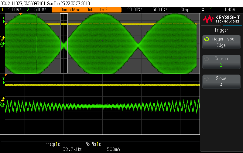
Math, FFT & Reference Functions
Math Function
The math and FFT functions also display noticeable differences between the two scopes. With regards to the math function, Keysight has seven operations available, addition, subtraction, multiplication, division, FFT (|x|), FFT (𝛉) and low pass filter (1Hz - 100MHz). There is also a secondary (internal function) that can be used for the FFT to select internal operations (addition, subtraction and multiplication) to be applied to the channels before the FFT is applied. Tektronix only provides three of these namely, addition, subtraction and multiplication. While the other operations might seem unnecessary, when working with analog circuits theses operations can be and are helpful.
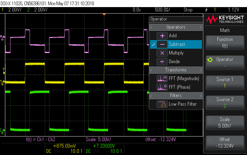
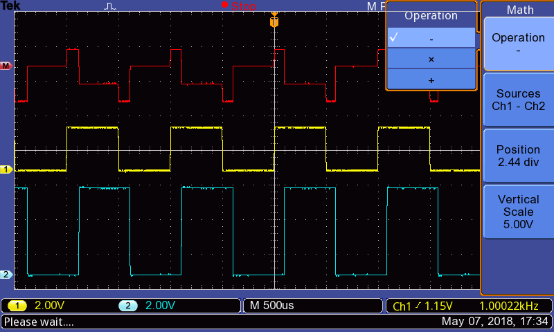
Math functions available with the Keysight DSOX1102G and Tektronix TBS 1202-EDU respectively
FFT
Another clear difference between the two scopes can be seen in the implementation of the FFT. Tektronix has opted to display the signal waveform in a separate window above the FFT waveform or not at all. Keysight on the other hand overlays the FFT over both analog channels, but still keeps them visible in the background. When selected, Tektronix only displays the waveform being analyzed but, the full waveform is visible. Other than the way in which each scope chooses to display the FFT waveform there is a more tangible difference. Tektronix uses the vertical scale to select the dB per division and the vertical position to move the waveform up and down. The waveform is shifted using the horizontal position knob and the horizontal scale is used to change the frequency per division. You can not really set the span or center frequency of the waveform. Keysight allows for the previously mentioned settings to be set (scale and offset). However, instead of setting the frequency per division and shifting the waveform, Keysight allows you to set the center frequency and the span. This gives more control of the waveform being displayed as well as makes it more intuitive as to what is being displayed.Tektronix provides zoom functionality, what this provides is not quite clear or intuitive. One more thing to note here is the vast difference in number of sample points used to generate the FFTs. Keysight uses 65536 sample points compared with just 2048 from Tektronix. This increase of 32 times allows for a smoother more accurate FFT waveform.
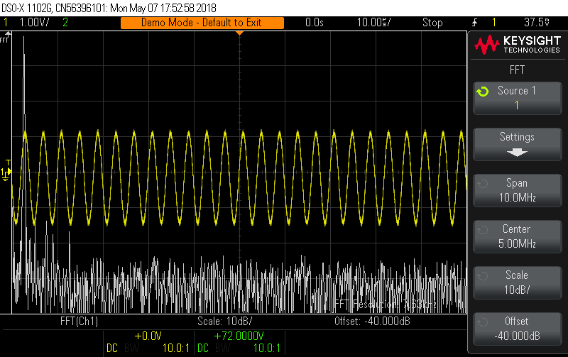
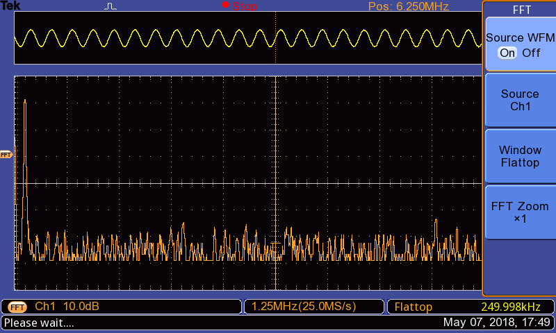
FFT waveforms along with the original waveforms shown on the Keysight DSOX1102G and Tektronix TBS 1202-EDU respectively
Reference Waveforms
While reference waveforms may not be used often, especially by users just learning to use a scope , they are useful. It is even more useful when trying to understand how a waveform changes with different component values. The reference waveforms implementations once again display noticeable differences. Both scopes allow for you to save two reference waveforms locally, and as many as you like via USB. However, Tektronix allows you to display both reference waveforms at the sametime. This is useful to see how a waveform changes with different component values or environmental conditions. Keysight has selected to only provide the ability to display one reference waveform at a time. Keysight does provide other useful features. Because not all reference waveforms line up perfectly, Keysight enables you to both change the scale of the waveform as well as shift it along the time axis. Another nice feature from Keysight is the ability to save math waveforms as a reference waveform. This is helpful again, when debugging analog circuits.
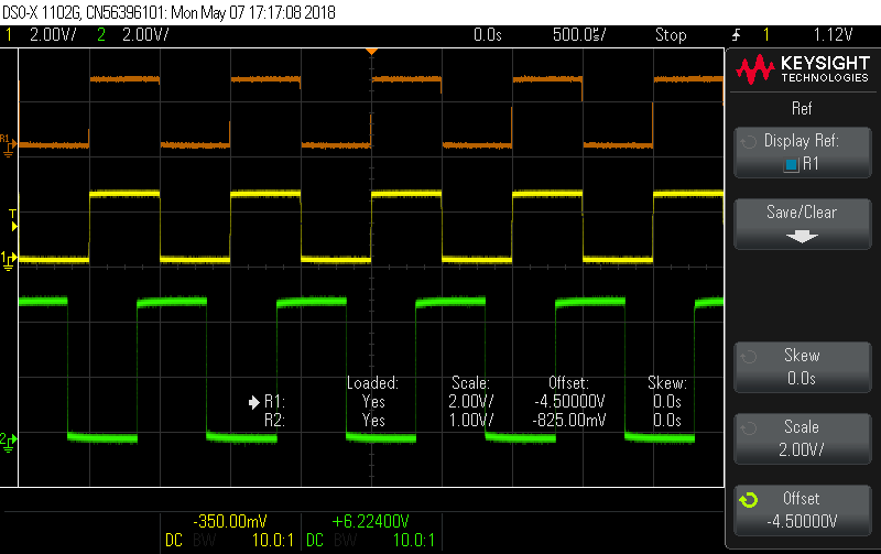
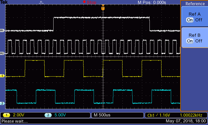
Reference waveforms and functions visible on the Keysight DSOX1102G and Tektronix TBS 1202-EDU respectively
Additional Functions
WaveGen
A useful instrument included as part of the DSOX1102G is a WaveGen. This addition to the scope provides 4 standard waveforms and two other outputs. These include sine, square, ramp and pulse waveforms as well as as well as a DC output between -5V ~ 5V and a noise generator. The waveforms can be set between 100 mHz ~ 10 MHz (except the ramp, upper limit 200 kHz). The amplitudes are adjustable between 2 mVpp ~ 20 Vpp (except sine and noise functions, upper limit 12 Vpp - pulse, noise lower limit is 1 mVpp). The 4 waveforms can also have noise imposed on the signal allowing for such things as noise rejection testing. Besides adding noise to a signal both the sine and ramp functions can be modulated as an AM, FM or FSK signal. The WaveGen does not cover all the functions offered by a conventional function generator, it's not supposed to. The intent is to allow for basic testing of analog circuits by injecting simple waveforms into the system and using an oscilloscope to evaluate the performance.
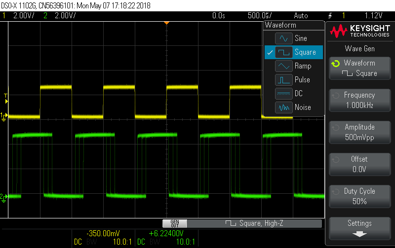
WaveGen waveform menu and setup options
Bus Decoding
The bus decoding capability is useful for simple digital debugging. With 5 types of serial buses available to decode (CAN, LIN, I2C, SPI and UART), the most commonly used protocols are covered. Each type of protocol has its own setup options. CAN allows for 6 different signal types, various sample points as well as the sample threshold to be set. There are also counters that show total number of received frames, number of errors and the bus load. LIN lets you select either LIN 1.3 or LIN 2.x giving a larger array of signals to be decoded. Unlike CAN there are no counters available for the LIN protocol. Lastly UART/RS232 allows for the number of bits to be between 5 ~ 9 bits, the parity (odd, even, none) , the polarity as well as the order of the bits (MSB/LSB first) to be set. There are other setting that can be changed (HEX, Binary or ASCII decoding) that make the use of the bus decoding a useful tool.
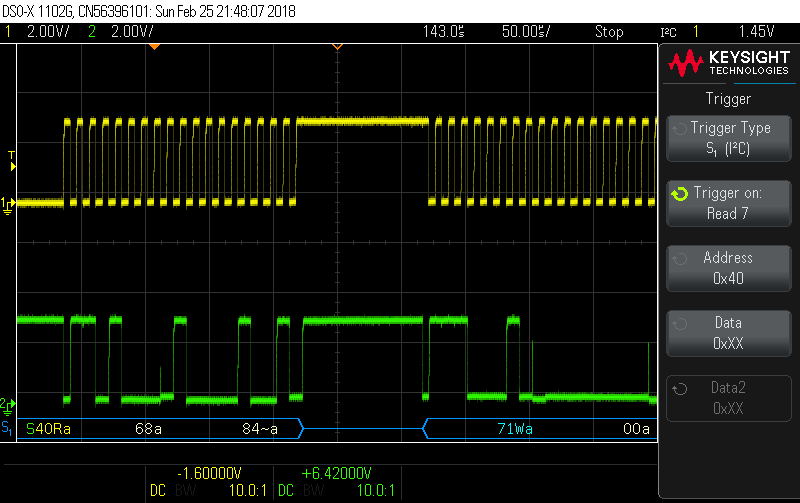
Bus decoding of an I2C signal
In conjunction with each of these bus protocols is the option to trigger on their various parts. This makes finding glitches or errors in messaging simpler. Because the analog waveform displayed just above the digital decoding, if there are any issues the true waveform can be analyzed for defects helping to resolve issues.
Mask Test
Masking allows a user to find infrequently occurring artifacts with minimal effort. Not having a touch screen makes setting up a mask more complex if anything other than the AutoMask feature is used. The AutoMask uses the waveform currently displayed on the display then adds a buffer around the waveform (∓Y & ∓X) ranging from 0V ~ 4V. Statistics are displayed on the screen (number of tests, failing rate, start time duration, etc) giving a more complete picture of testing results.
It is possible to write a mask file that is then uploaded to the scope. Unfortunately the information on how to do this is lacking in its explanation leaving someone wanting to do this guessing what some of the commands are for. It would be useful if Keysight created a PC application that would allow locations to be selected on a virtual display and generate a mask file for you. If a screen shot from the scope could be uploaded to this application it be that much more usable for those trying to use the mask feature.
The test can be run for a set number of tests, a minimum amount of time a minimum sigma or in manual mode. Upon failing a test there are several options that can be selected. The test can be stopped or the screen freezing for immediate evaluation, the waveform can be saved or printed for error logging and lastly a measurement can be taken to quantify the error.
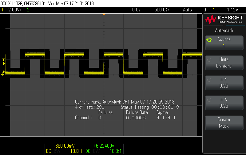
Using automask to find glitches and inconsistencies within a signal
Frequency Response Analysis
A really useful feature and one that fits in with what an oscilloscope is often used for is the frequency response analysis function (FRA). The FRA leverages the analog measurement from the scope as well as signal output from the built in WaveGen. By connecting channel 1 to the input of the device under test (DUT) and channel 2 to the output, the system response can be measured. While this may produce a rough measurement, for an entry level piece of equipment the measurements are acceptable and helpful. This allows those wanting to characterize parts of a circuit or a whole circuit to do so without needing extra equipment.
The settings allow for a wide range circuits to be tested. The available frequency range is 20Hz ~ 20MHz, and the start and stop frequency can be selected anywhere within that range. Lacking is any information on what step sizes are used or how many sample points are used for this analysis. The peak to peak voltage can also be set between 1 mVpp ~ 9 Vpp ensuring no clipping or damage occurs to the DUT.
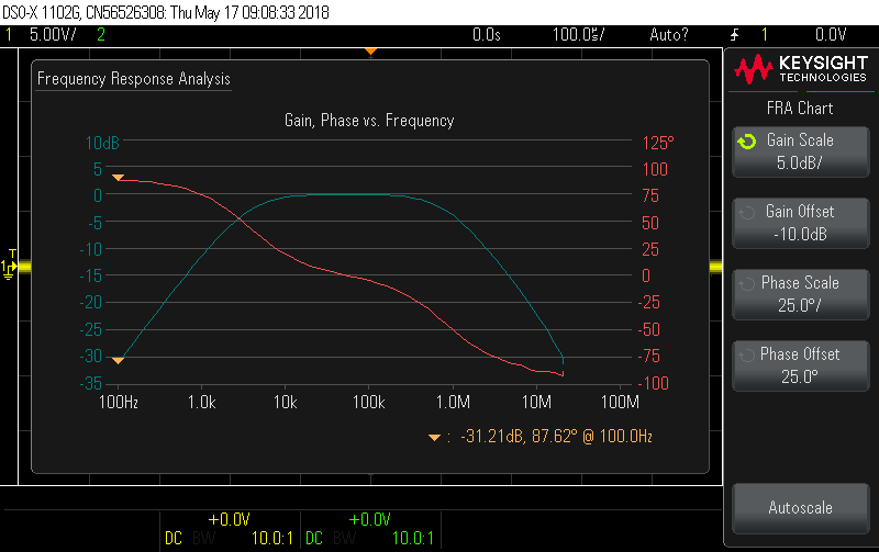
FRA measurement results with a bandpass filter from Keysight
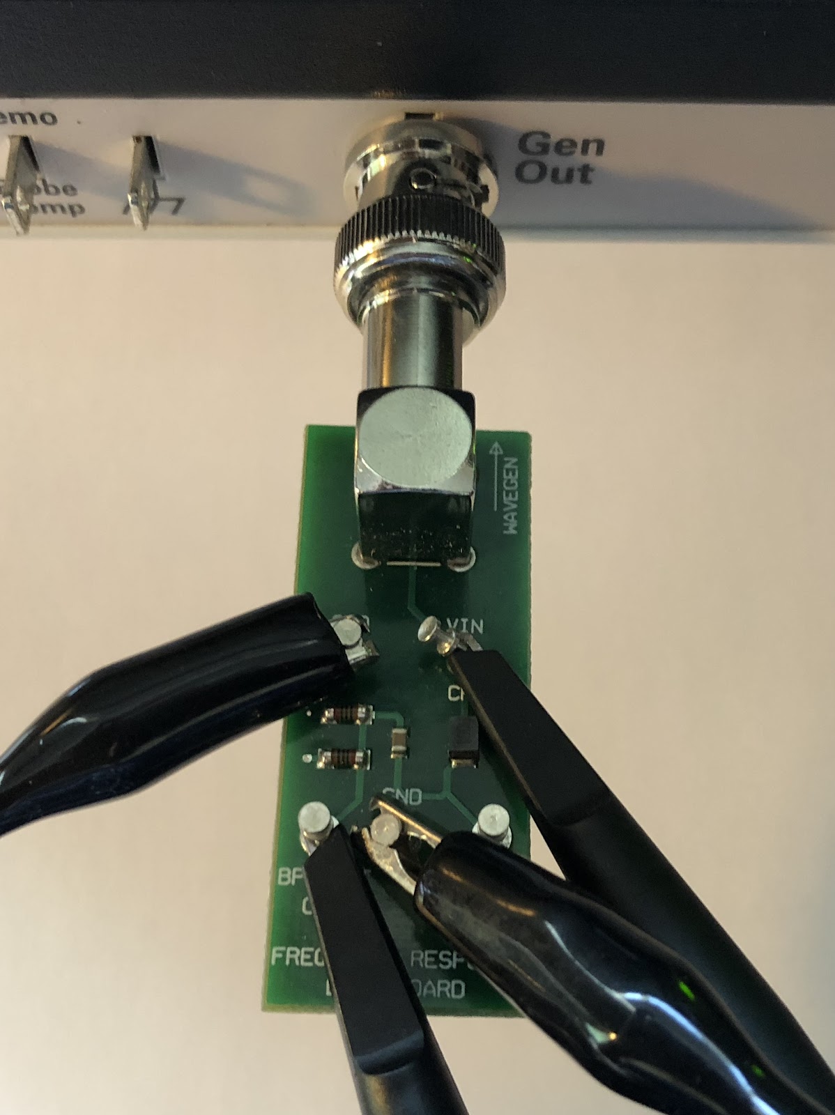
Keysight Bandpass filter board for FRA testing
Conclusion
While this review has covered a lot of the functionality offered by both oscilloscopes not everything was or could be covered. There are some things that may only be useful to a small subset of users or may have minimal impact on the selection of a scope. These things have been left out in this review but may be looked at when these scopes are used in the evaluation of circuits used in future blog posts.
As previously stated, these two oscilloscopes are really not on an even footing, even though they are both entry level scopes. Keysight has clearly put a great deal of effort into their end product. The intuitiveness of the layout and menu settings makes the unit that much easier to use. This is not to say that Tektronix has not provided some nice features, it's more that they have added these at the expense of having an overall great product. Keysight has also added features to make their scope a complete test center for those starting or on a budget. The ability to use test waveforms to see how a circuit responds is very useful. The bus decoding, though not a full logic analyzer, adds some great functionality especially with regards to triggering. In response Tektronix has added courses to their scope or for the non-educational model, trend plots and limit tests. These may help and be somewhat interesting but, limit tests are nothing more than the masking offered by Keysight. Trend plots may be the only differentiator but, alone does not make the scope stand out from others in its class. Added to this is the sluggish response of the Tektronix scope, altering setting should be a simple matter and not a task in of itself. The price point of the two scopes does not help the situation either. Keysight has priced their scope, with all the additions, at half the price of the offering from Tektronix.
Over all Keysight has brought a wonderful offering to the entry level space. When I was looking into this scope I was informed that its core is the same as the higher end DSOX’s but with a lower bandwidth, sampling rate fewer channels and no touch screen. From my experience using this scope and working through each of the functions I would have to agree with such a statement.