Showing posts with label logging. Show all posts

Wednesday, October 4, 2017

MangOH Red Launch and Legato Framework


Sierra Wireless has just launched their newest offering in the IoT space. The MangOH Red is a smaller and more compact board than it's older brother the MangOH Green. Aimed at a being used in an end product rather than the development, the board resembles the footprint of the Raspberry Pi. With onboard Bluetooth and WiFi, the MangOH Red is ready to be used in any IoT application. Still standard are the CF3 modules with their on chip cellular connectivity and GLONASS and GPS positioning capabilities. The CF3 module cellular options include 3G, 4G LTE and LTE-m1/NB-IoT modules.

MangOH Hardware

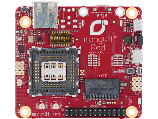
The MangOH Red has a notably different hardware setup from the MangOH Green. Being more compact, the MangOH Red has one CF3 slot and one IoT expansion card slot. Because the MangOH Red has onboard bluetooth and WiFi there is an onboard antenna as well as  u.fl connector to allow for an external antenna to be attached for these services. The other previously supported antenna connections (cellular, Glonass and diversity) are all still provided. No longer provided onboard is ethernet, RS323 and the arduino shield connector. For the users who may miss these, they are still available via the IoT expansion cards. The debugging interface has been made simple with a micro USB connector.

New to the MangOH Red are pressure, light and temperature sensors. These new sensors along with the IMU gives the board spacial awareness right out of the box. Also new the the MangOH Red is a Raspberry Pi Hat connector. This allows for the more complex and capable boards designed for use with the Raspberry Pi to be used with the MangOH Red.  Built in battery charging and monitoring circuitry allow for a rechargeable battery to be added. With this setup Sierra Wireless has made a product that a true IoT board that is ready to be deployed anywhere monitoring is needed.

Unboxing and Setup

The MangOH Red comes in a neatly packed box with everything you need to get started. One big improvement from the MangOH Green is the inclusion of a universally compatible sim card. With 100MB of data this is enough to get anyone started with the demos and basic applications. Setting up the MangOH Red is quick and easy The WP module is slipped into the module holder and the cover snapped closed. After connecting the cellular antenna all that is left to do is connect the USB cables. These are used to provide power and access to the console. While it is possible to provide power from either USB cable, access to both the console and CF3 module via SSH is useful.

The documentation for the MangOH Red has been revised and updated from the MangOH Green. This new revision has produced a clearer and more concise set of documents. The initial setup time, from out of the box to getting the demos running has been reduced with the aid of better step by step instructions. The “MangOH Red Setup Guide” is especially helpful in getting the system setup and performing its first set of data logging to the cloud.

After everything has been connected the hardware is ready to be used. Upon powering up the system, you will need to work through the getting started guide. This will setup your environment on your PC as well as install the latest applications on the MangOH Red. The only issue encountered was a change in RSA key which the command line explained how to resolve.
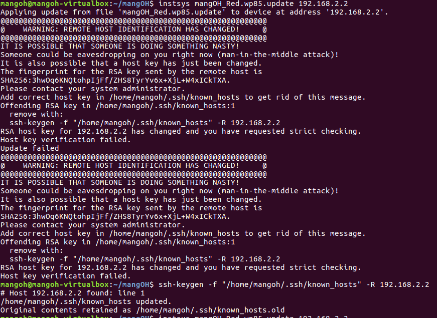


Once done, completing the installation is easy and smooth. The rest of the getting started guide follows the same well explained step by step paradigm. As the rest of the setup and getting started is self explanatory we’ll move to the software structure of Legato used by the MangOH

MangOH Software - Basic Structure

The MangOH boards use the Legato framework as the basis for their software. The Legato framework provides a lot of APIs take care of the simple as well as to simplify the more complex tasks that can be performed with the MangOH boards. The framework, while well thought out and logically ordered, can take some time to get used to for those just starting out. The basic file structure as well as the chain between variables and peripherals will be explained below.

Basic organization of the Legato file structure

The first folder (application folder) acts as a container for the application and is often named with the name of the application. This folder contains the application definition file as well as the component folders. The application definition file (adef) allows the compiler to know what components are used in the application as well as what peripherals are required. The adef also binds external hardware or devices to internally used variables.

Application Definition File (ADEF)

Using a very simple example we will look at the heartbeatRed application. In this application which uses very few resources and has only one component the  the adef looks as shown below. Starting from the top, the executables defines what code should be run in this application. In this snippet the heartbeatComponent is what we would like the application to run. Since a component can be run with multiple instances each instance is given a unique name. In the code below there is only one instance named heartbeat. Now that the instance has been named, we let the system know under processes that we would like this instance to be run. To do this we place the instance name heartbeat in the subsection run. This will start the application when the system loads (provided we have put on line 3 “start: auto” and not “start: manual”). If it is set to manual, you will need to do: app start heartbeatRed. Lastly there is the bindings section. This links the external devices (ports, files, etc.) to variables the software can use. In the code below we would like to be able to control pin 34, this is the onboard LED. To accomplish this the variable mangoh_led which is found in the heartbeatComponent and is part of the heartbeat executable is connected to the  gpioService. This service through the Legato GPIO service  then connects the variable to the specified pin.

sandboxed: true
version: 1.0.0
start: auto

executables:
{
   heartbeat = ( heartbeatComponent )
}

processes:
{
   envVars:
   {
       LE_LOG_LEVEL = INFO
   }
   run:
   {
       ( heartbeat )
   }
   faultAction: restart
}

bindings:
{
   heartbeat.heartbeatComponent.mangoh_button -> gpioExpanderServiceRed.mangoh_gpioExpPin14
   heartbeat.heartbeatComponent.mangoh_led -> gpioService.le_gpioPin34
}
heartbeatRed adef file as found in the heartbeatRed application folder

Component Definition File (CDEF)

Now that we have shown the compiler what components are to be included as well as what devices are needed and provided a handle for components to access them, let's look at the file that explains how the component is put together. The component definition file (cdef) explains how the various files are integrated as well as what source files the component needs to be correctly compiled.
As mentioned in the adef, we would like to have access to peripherals and as such we have linked a variable to them in the adef. In the cdef we now connect them to an API to allow us to manipulate and interact with these hardware or service components. This is done in the requires section by listing the variable in the api subsection and linking it to the required API. In this code snippet we need access to the gpio API, the mangoh_led variable is therefore linked to the le_gpio.api. The other section in this code snippet lists all the source files needed by the component to function correctly.

requires:
{
   api:
   {
       mangoh_button = ${LEGATO_ROOT}/interfaces/le_gpio.api
       mangoh_led = ${LEGATO_ROOT}/interfaces/le_gpio.api
   }
}

sources:
{
   heartbeat.c
}
Component.cdef file as found in the heartbeatComponent folder

Source Code

Let's now have a quick look at the source file that makes up this component and controls how the LED behaves. Below is the full source code for this component it is the code listed in the cdef and used to turn on and off the onboard LED. The first thing to note is the inclusion of both legato.h and interfaces.h. The first allows us to use any of the legato header files used by the component, all legato programs will use some legato header. The second file include.h links in the auto generated header file from the cdef.

Moving further down the code we see in the function LedTimer a variable called mangoh_led_Deactivate, this variable is created through the binding section in the .adef file. In essence this is using the variable mangoh_led, created in the cdef and linked to hardware in the adef, with the api. We are therefore saying the variable mangoh_led should be used with the function call Deactivate to turn off the specified pin. This same principle applies to the other variables in the code that use the legato APIs. The next function, ConfigureGpios sets the pin with the LED attached as an output. If this fails the legato API is then used to send a message to the system log using LE_FATAL_IF. This ability set in the cdef under envVars and allows the system to log messages at the info level and lower.
The last and most important part of the C source file is the COMPONENT_INIT. This is similar to main() in C programs but, because there is no main() in legato applications, we need a different entry point. The COMPONENT_INIT is this entry point. It is important to note though, that unlike main functions this function must return. If COMPONENT_INIT does not return then the rest of the application will not run. In this specific COMPONENT_INIT function a timer instance is created to control the intervals between turning on and off the LED. After an instance is created various parameters for the timer (period, whether to repeat or not as well as its handle) are set.  Lastly the gpios are configured using the previously created function and the timer is then started. After all this is done the COMPONENT_INIT is exited and control is handed back to the legato framework.      

/**
* @file
*
* Blinks the user controlled LED at 1Hz. If the push-button is pressed, the LED
* will remain on until the push-button is released.
*
* <HR>
*
* Copyright (C) Sierra Wireless, Inc. Use of this work is subject to license.
*/

#include "legato.h"
#include "interfaces.h"

#define LED_TIMER_IN_MS (1000)

static bool LedOn;
static le_timer_Ref_t LedTimerRef;

/*------------------------------------------------------------------------------------------
* Toggle the LED when the timer expires
*/------------------------------------------------------------------------------------------
static void LedTimer(le_timer_Ref_t ledTimerRef)
{
   if (LedOn)
   {
       mangoh_led_Deactivate();
       LedOn = false;
   }
   else
   {
       mangoh_led_Activate();
       LedOn = true;
   }
}

/*------------------------------------------------------------------------------------------
* Turn the LED on and disable the timer while the button is pressed. When the  button is
* released, turn off the LED and start the timer.
*/------------------------------------------------------------------------------------------
static void PushButtonHandler(bool state, void *ctx) //
{
   if (state)
   {
       LE_DEBUG("turn on LED due to push button");
       le_timer_Stop(LedTimerRef);
       mangoh_led_Activate();
   }
   else
   {
       LE_DEBUG("turn off LED due to push button");
       mangoh_led_Deactivate();
       LedOn = false;
       le_timer_Start(LedTimerRef);
   }
}

/*--------------------------------------------------------------------------------------------------
* Sets default configuration LED D750 as on
*/--------------------------------------------------------------------------------------------------
static void ConfigureGpios(void)
{
   // Set LED GPIO to output and initially turn the LED ON
   LE_FATAL_IF(mangoh_led_SetPushPullOutput(MANGOH_LED_ACTIVE_HIGH, true) != LE_OK, "Couldn't configure LED GPIO as a push pull output");
   LedOn = true;

   // Set the push-button GPIO as input
   LE_FATAL_IF(mangoh_button_SetInput(MANGOH_BUTTON_ACTIVE_LOW) != LE_OK,
"Couldn't configure push button as input");

   mangoh_button_AddChangeEventHandler(MANGOH_BUTTON_EDGE_BOTH, PushButtonHandler, NULL, 0);
}

COMPONENT_INIT
{
   LedTimerRef = le_timer_Create("LED Timer");
   le_timer_SetMsInterval(LedTimerRef, LED_TIMER_IN_MS);
   le_timer_SetRepeat(LedTimerRef, 0);
   le_timer_SetHandler(LedTimerRef, LedTimer);

   ConfigureGpios();

   le_timer_Start(LedTimerRef);
}
heartbeat.c source file as found in the heartbeatComponent folder

While this was a rather simple and easy to follow demonstration it outlines the most important parts of setting up a legato application. The most complex and important part of this example is how variables are linked to the device or hardware they wish to control. The adef links the device to a variable name. The cdef then links this to an API which the source code can then use to interact with and manipulate the device.

I am planning on releasing another blog post shortly that will explain the more complex redSensorToCloud application. This application has multiple components and uses linux drivers for some of the peripherals.
Friday, October 28, 2016

Keysight U1282A Digital Multimeter - Review and IP67 Rating

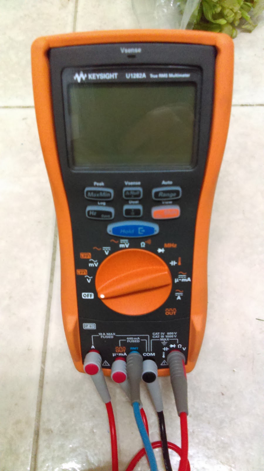
IMAG1342-1.jpg

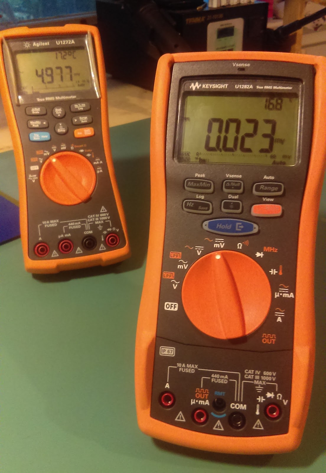
I would like to thank Element14 and Keysight for selecting me to review the U1282A. Keysight, formerly Agilent Technologies, is a leader in electrical test equipment. While Keysight has been steadily expanding there multimeter offering, the U1282A is the newest in their lineup and first general purpose multimeter to be IP67 rated.

Unboxing and First Impressions

The U1282A comes nicely packaged as most of Keysights multimeters do. The overall presentation when opening the box for the first time is product built to be used hard and to last. The box comes with a built in divider to keep the multimeter separate from the accessories. The leads were neatly tied up in a ziplock bag unfortunately, there was no protection to cover their sharp points. The included test leads appear stiff and at the first chance I had, I swapped them out for a pair that came with my U1272A. Next to the leads was the IR-USB connector to allow for remote data logging as well a firmware upgrades. The inclusion of the IR-USB adapter is a much welcomed decision. As a good deal of problem solving is done over an extended duration being able to record data for that duration is a big help.

IMAG1331-1.jpg
Unboxing the Keysight U1282A

Neatly folded on top of both the multimeter and accessories was the “Quick Start Guide” and certificate of calibration. It should be noted that if you ever lose your certificate of calibration and want a copy, Keysight has all the calibration data for each multimeter by serial number.

Reason for Application

I applied for the this road test because of my ongoing work reviewing new products. In this capacity the environments and issues and very wide spread. Some products work in or around water, making the IP67 rating very useful. Other products are supposed to be low power and having a second meter that can perform logging allows for DC power to be easily monitored. Still others are connected to mains power and the ability to quickly determine if the system is live or not can greatly increase the level of safety.

After watching Keysight’s promotional videos demonstrating their IP67 compliance I felt they were weak and unconvincing. Because of this I was very much interested in doing my own real world and maybe slightly exaggerated testing.


Another function I was interested in to exploring  was the PWM output. During testing there are times a servo or other PWM controlled device that may appear to not work. Having a known good PWM output can save many hours of troubleshooting. I as therefore curious to see if the PWM from the U1282A could be used as a test PWM for servos.

The last major U1282A function I wanted to evaluate was the Vsense. This function allows you to determine if a wire is live without making an electrical connection. This has the potential to make tasks a lot safer provided it works correctly all the time. Seeing as the number of inline devices or those attached to the mians are also increasing this would help increase the safety during my tests.

I should mention that there was never any intention to look at the accuracy of the U1282A as this is something Keysight is known for. I have only ever heard of one case where a new meter performed incorrect measurements. While this meter did have a calibration certificate this was probably a once of occurrence. I’m also sure that the are others that have reviewed the U1282A and have better means to test the accuracy and repeatability of the meter.

Sand Test

The first issue I wanted to cover was the demo videos from Keysight. As previously mentioned they seemed weak and unconvincing regarding true reliability of the meter. While Keysight did cover the meter is sand there was no attempt to move the selector dial or engage the meter in any mechanical use until after the sand was removed. Also the meter was at one point wetted before covering it with sand trapping the sand on the exteriors of the meter. This has the added benefit of reducing any penetration of sand into the selector dial and the connector terminals.

In the mentioned video the sand was promptly washed off after each time the unit was exposed to sand. In a real world situation we do not get to choose the order the meter is exposed to sand and water or how much of each. Also a bucket of water is most likely not readily available to wash off the sand before the job is completed. Whether it is possible to clean the meter or not, it would still need to be used and function without issue. It should be noted that washing off the meter would render it inoperable until it is dry due to the input warning (leads in wrong input).

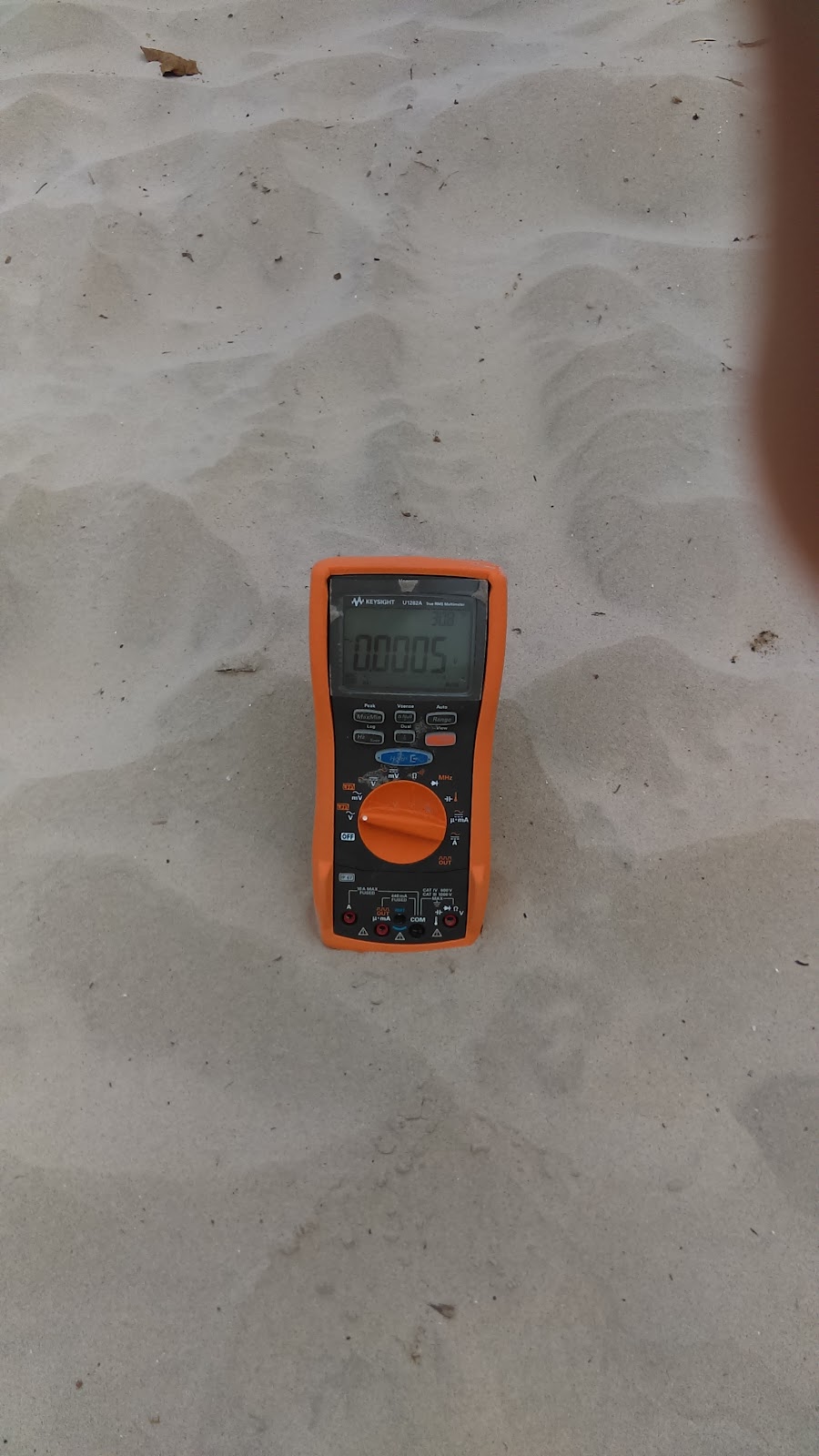
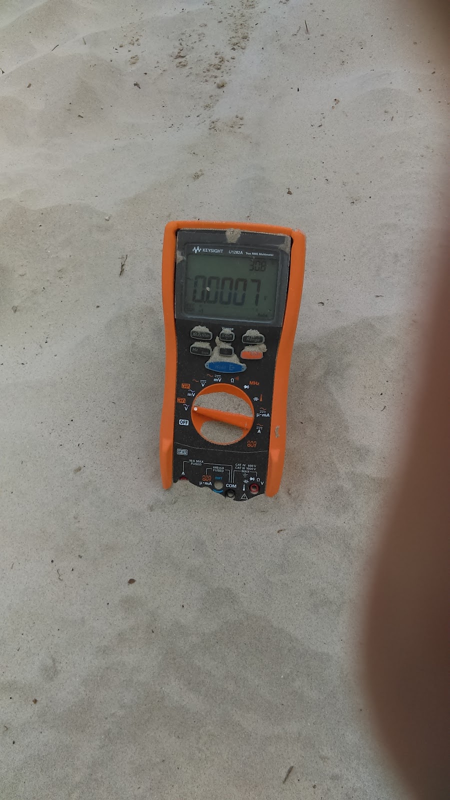
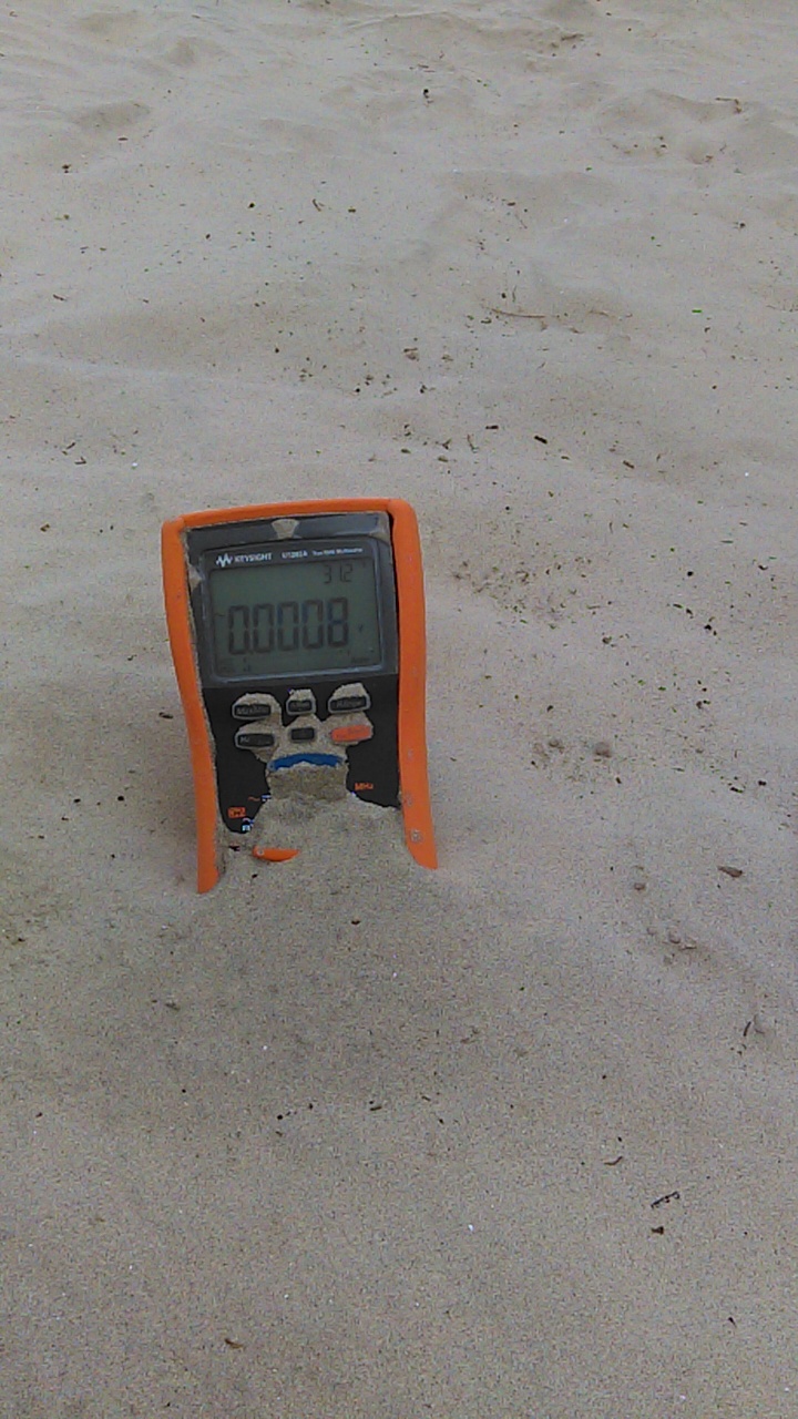
In the testing I conducted the meter was completely covered with beach sand. While this may be finer than some sand commonly found, this is with in the size specification for the IP rating. This grain size would also have the potential to be blown around by the wind and into the crevices of the meter making this a valid test. After being subjected to the sand the meter was than cleaned off. This included being brushed off,  washed off with a “hose” as well as rinsed in a bucket. The complete procedure, the meter being covered as well as washed off can be seen in the videos below.
.
IMAG0145.jpgIMAG0149.jpgIMAG0152.jpg


Immediately it can be heard that here is a decent amount of sand in the dial. Even with the background noise of the water and wind the grinding is unmistakable. The meter was then thoroughly washed off in a bucket of water as well as with a squirt gun.


The meter can unmistakably be heard being ground away by the sand stuck between the selector dial and the housing. While it may be considered slightly unfair to operate the selector dial while not completely cleaned from sand, this would most likely be done in a real situation. It should be noted that even with the wind in the background the sound is unmistakable. Also while the Keysight test appeared to show no sand in the dial after being washed off, this was clearly not the case here.

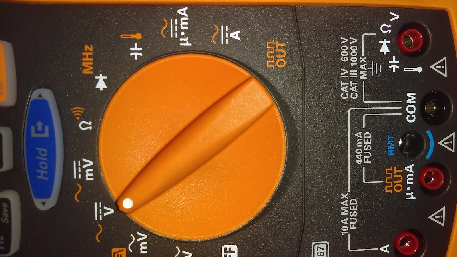
While this may seem like just an annoyance this could conceivably lead to product failure. Specifically this could lead to a breach of the housing allowing water or sand into the housing.This is clearly unacceptable for the IP67 standard, any interference with the satisfactory operation of the unit is considered an issue. The wearing away can be seen in the below picture. In this case the dial was rotated a few times (> 5) producing plastic filings around the AC volts and millivolts section of the dial.

IMAG0312.jpg

Unfortunately there were only two available solutions to remove the sand. Either send the unit back to Keysight for cleaning or void any calibration warranty and clean the meter myself. Thankfully Keysight took the issue seriously and decided to consider this an “out of the box defect”. In this case the unit was repaired under warranty. I would like to mention that while this issue was being addressed by Keysight internally there was little consensus as to the classification of this issue. The product manager as well as the local FAE appeared to agree that this level of damage to the product should not occur. In contrast the design and test team appeared to be of the opinion that the testing I performed was not valid and the unit behaved as it is designed to and in accordance with the IP67 rating.

I have checked with the respective team, and we found that it is an expected behavior that the sand may ingress between the rotary switch and the top case. However, the sand will not go inside PCA level of the meter. “

After asking for further clarification due to the grinding of the plastic I received only instructions on how to send the unit back. There was no further information on how the plastic would not be ground down potentially causing a hole in the casing.

Water Test

The water test conducted by Keysight was for the most part sufficient. The meter was submerged and shaken around allowing for water to flow all over the unit. It is true that the meter was not submerged for the required 30 minutes but that was less of a concern considering others have put the meter through that testing. Also with regard to the water tight seals on the unit I don't believe I could do a better test than that conducted by Dave Jones. In his test the meter was submerged, dropped and abused in a very wet and demanding environment. Through all the testing the meter continued to work as designed.

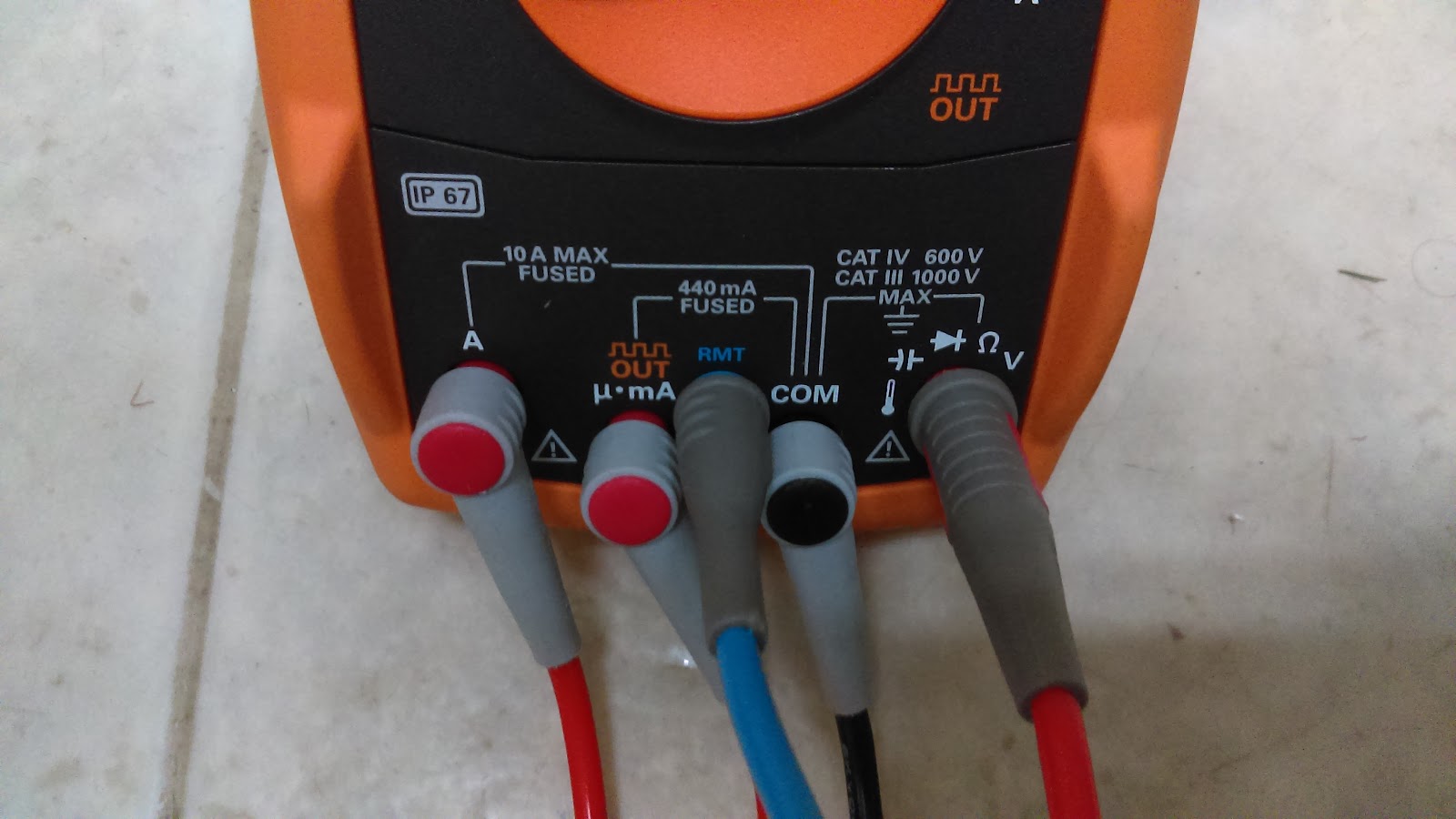
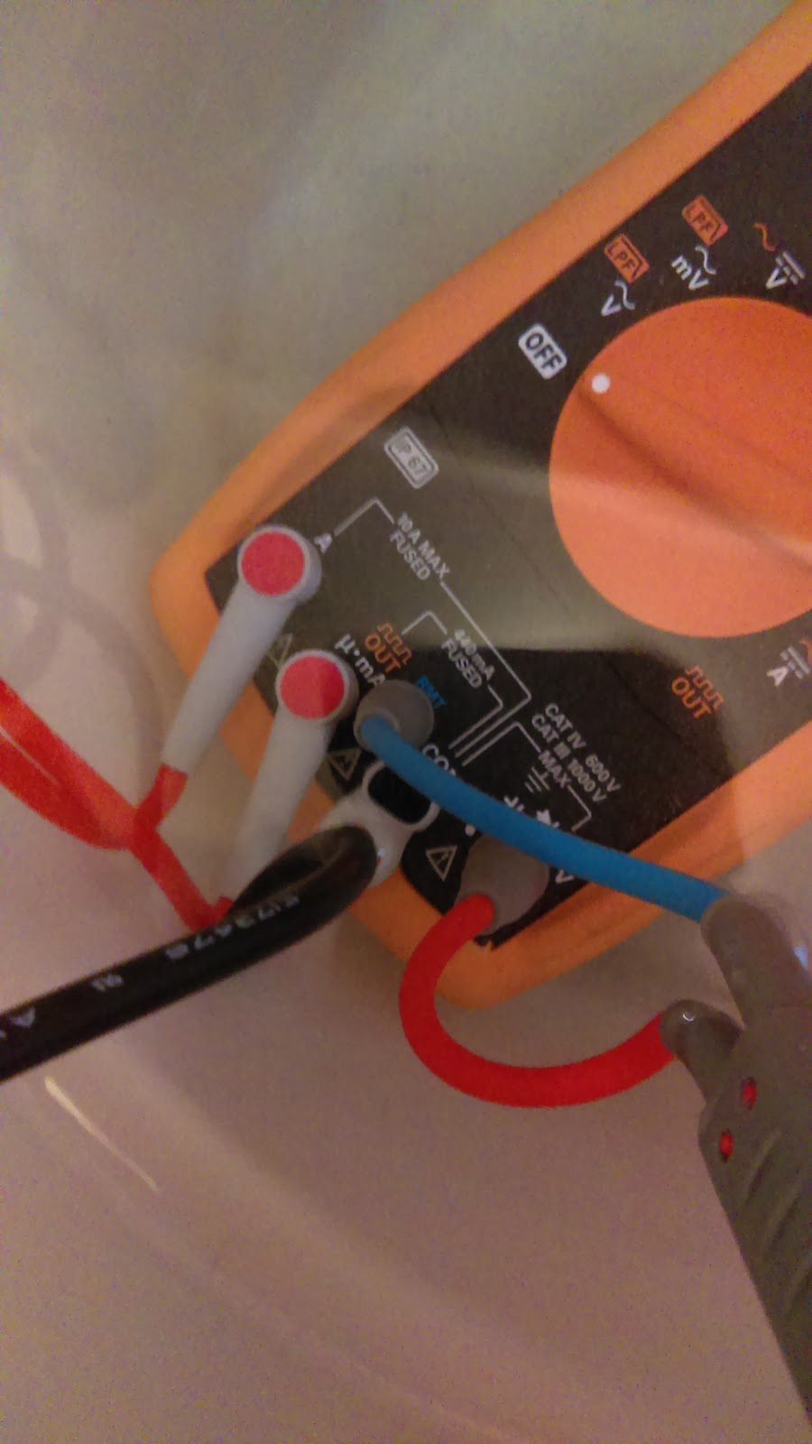
What I have done different than all other water tests to date was to submerge the unit with all input terminals plugged with a test probe. While this would normally not be done and it does sound the input warning alarm, it was done to keep the water out of the terminals. Something I have mentioned to a number of Keysight personal (sales reps, FAEs etc.) is that plugs should be included in the kit or at least be available. The reason is that although the unit is waterproof the input warning will sound until the inputs are fully dry. While the IP67 rating ensures I will not damage my meter if it falls in water or gets wet my testing will be on hold for ~45 minutes or more until the probe terminals are completely dry. Keysight does ship their meters with dust plugs for the test leads and probes, which are sealed when in the field. in contrast to this, there are always at least 2 terminals left open to the elements for dust and water to get in, something is not making sense in this decision.

IMAG1283.jpg
IMAG1284.jpg
IMAG1290.jpgIMAG1288.jpg
U1282A with all terminals capped while the meter is submerged

Test and Results

After inserting a lead into each of the 5 terminals the unit was submerged and splashed around a bit. The unit was turned on, the selector switch was rotated. While the unit was on the input warning sounded as expected. Once the water portion was complete the unit was taken out of the bucked and an air hose was used to dry the area around the leads.

When the extra two leads were removed the input warning did not sound. This was tested in all three variations. That is in volts, milliamps and amps mode, in all cases when the leads were inserted correctly the alarm did not sound. This furthers my question why Keysight does not include plugs with the unit for those doing testing in a wet environment.

Customer service

As mentioned above testing the unit in a sandy environment resulted in the selector dial becoming contaminated with grit. Since this was a road test Keysight was looking to keep things as positive as possible. Also because the issue was reported within 30 days of receiving the unit they decided to treat it as an out of box defect.

Unfortunately the process for taking care of this was a little bit convoluted and complex. While I was offered upfront to have the unit repaired I was hoping to get more info on the IP67 rating. This additional information never did come and there is still no clarification on what he unit should or should not be able to handle.

Experience with the return

Part of the reason for such a delay in this review has to do with the repair customer service. The amount of time it took to contact the product manager or anyone that could/would seriously help me was pretty extended. The product manager then needed to contact Malaysia and as well as the design team. Eventually I was informed Keysight would cover all cost in having the unit repaired. I was graciously offered to have the unit picked up from wherever was convenient for me, at home of from the office did not matter. In order to speed up the process I had it picked up from my home as this was closer to the sales representative and would allow for faster pick up.

While the unit was picked up the same day that I was contacted by the local office the whole process in having the unit repaired took substantially longer. I the unit wa shipped back to Malaysia where it was disassembled and cleaned. Then the unit was shipped back to the local office and than to me. In all the process took 6 weeks and 5 days (June 23 - August 9). For a piece of test gear that I would potentially use daily on the job, being without it for almost 7 weeks is unacceptable.

PWM Control (Servo Control)

Having a known valid PWM output is very handy especially when testing parts sent to you for evaluation. As a product tester/evaluator I test various products and devices. One of my recent projects was a robotic hand with 6 DoF. Unfortunately there was an issue with the servos not working as they should. Using the U1282A as a calibrated and valid PWM source made it a simple matter to test whether the issue was the servo or the controller.  

For this setup a 5V supply was connected to the power and ground leads on the servo. The U1282A was connected to the signal line and ground. The servo responded as expected it should with a valid PWM signal. This demonstrated the ease with which a PWM device could be debugged with the meter.

Video of meter controlling servo and scope showing changes of width

Since some servos still demonstrated some issues, the PWM output was connected to a oscilloscope. This again verified that the output appeared to be correct. The U1282A was also connected to a U1272A which has a frequency counter as well as a PWM deconstructor. This outputs the duty cycle as well as the period. Sadly the numbers displayed by the two meters had a significant discrepancy. After mentioning this to Keysight I was informed the U1272A needed a factory reset (not sure how this affects measurements but… ). This sadly did nothing to help remove the discrepancy.

Video of meters showing different numbers

VSense

The last major function of this meter that I was intrigued by was the VSense. This functionality allows you to test if a AC wire is live without needing to make contact. When working with live mains this is a major benefit. From testing inline IoT devices to troubleshooting a water heater this can seriously save you.

Before I got a chance to really test this functionality I found that my water heater was not behaving correctly. As part of the troubleshooting I wanted to be sure the heater was powered. When measuring the voltage between what appeared to be the two terminals a very low voltage was observed (~ 1V). Thankfully before working with anything I tested the circuit with the VSense and found there was still something live. On further inspection only one breaker was fully tripped. The second pole was still connected and was thus allowing something to creep through. I may not be 100% how I measured ~1V while the system was live but I am sure that without VSense things could have gone a lot worse.

I would like to mention that getting the VSense to behave predictably takes some time. When doing some of my further testing I found that there is a need to move the meter around slowly. This is because the sense location does not appear to always register in the same location. Also there are times you will need to change between high sensitivity and low sensitivity to be sure you are measuring the correct wire. Overall though the functionality is very useful and beneficial.

Recording Measurements

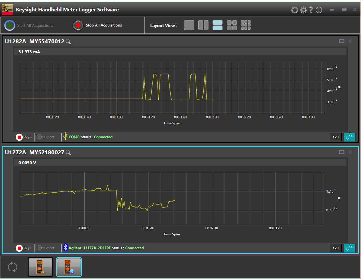
Another feature I wanted to look at, indirectly linked to the meter was the ability to log data remotely. Although this is not unique to the U1282A, the U1282A does put an emphasis on data logging. I have used previous iterations of Keysights data logging software with my U1272A with mixed results. While the update was relatively reliable things got worse when trying to log data. There were often times a value or multiple values were missed. Also, in previous iterations only one meter could be used at a time necessitating opening multiple logging windows. Having multiple windows compounded with missing data made the post processing very messy and and difficult to get usable and meaningful data.

In the newest version all these issues appear to have been taken care of. You can now connect to and log from up to 9 meters at the same time. There is also an easy way to either view the history of the data as a graph or as a meter display. The export function also works better than before, giving more options. Like Tektronix, Keysight appears to be realizing that good and easy to use software can be just as important as good hardware.
2016-10-05 16_01_01-.png
Keysight PC based remote logging software logging from two meters

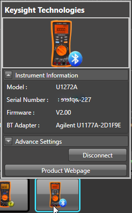
2016-10-05 15_54_41-Keysight Handheld Meter Logger Software-1.png2016-10-05 15_54_18-Keysight Handheld Meter Logger Software-1.png
The profiles of the connected meters as well as information on how they are connected

Conclusion

Overall this is a solid meter that as most if not all Keysight meters do, delivers good quality and is easy to use. Unfortunately from the IP67 rating as demonstrated by Keysight there is room for improvement or clarification. Most importantly the customer service experience needs a lot of help. Waiting 7 weeks to have a meter repaired is unacceptable.

If someone is looking for a meter that is reliable and delivers sound measurements, than any Keysight meter will do. The chances are someone would be choosing the U1282A for its IP67 rating. In that case I would differentiate between the IP6x and the IPx7. From the testing conducted by Dave Jones on the EEVBlog as well as my own basic testing I would say the U1282A is waterproof without an issue. Any environment that contains moisture or water the U1282A would work well in provided the unused terminals are covered. However, regarding the dust proof rating there are issues. The meter definitely has the ability to fail and the lack of clarification from within Keysight on what the meter should be able to withstand is also an issue. Lastly when the promotional video for Keysights version of IP6x involves covering the unit in sand, there should be no negative effects in doing so.

Based on these conclusions, for a wet environment I would recomend the U1282A but I would like to see Keysight add terminal dust caps to prevent water rendering the unit useless until completely dry. Unfortunately if the intended use is in an environment that contains fine grit sand (beach or desert sand) I don’t belive the U1282A will deliver what Keysight wants you to believe it will.

Update

This is a response from Keysight in relation to the delay I experienced in having the unit serviced: The repair delay you experienced wasn’t representative of typical handheld repair. Normally you’d call in, ship the unit to our local service center, it would be exchanged and you get a new one back. Due to your IP67 questions and concerns, your unit was picked up by me, returned to the factory in Malaysia, analyzed, repaired and returned which was not the normal process.  We took your feedback very serious.

Original post on Element14 can be found here