Showing posts with label Home Automation. Show all posts

Friday, November 11, 2016

Getting Started with the MangOH Green and Legato 16.07 on Ubuntu 16.04.1

IMAG1544-1.jpg

The MangOH Green is a board developed by Sierra Wireless to allow for easy development with their WP modules. These modules are specifically built for mobile/cellular IoT and have both cellular and GPS radios built into the chip. The MangOH Green runs a Linux application framework called Legato. Sierra Wireless has been working hard to keep the software moving forward. This has produced a number of versions each with subtle changes, and while there is a starter's guide for Legato that document has now become partially dated. This along with the relative newness of the manGO board and unique approach there is not a lot information to be found searching online, this however has been changing. As mangOH/legato becomes more popular the online content will also become more plentiful

With first hand experience as well as great help, from both the forums and mangOH personal,  in getting my MangOH board running I have decided to document the steps I followed to get the newest virtual machine version  “mangOH Dev using Legato 16.07 on Ubuntu 16.04.1” up and running.

The first thing to mention is the password for this version of the VM has been changed from “legato” to “mangoh”. While this has not been documented this was asked on the forums and has been answered. NOTE: This is only for 16.07 but moving forward the password will either be removed altogether or remain as “mangoh”.

The overall process follows a few basic steps each of which will be further explained below. The first step is to download and install the VM from mangOH. Then the firmware on the mangOH board should be updated. In the VM the environment variables are added to the batch file, the repository is updated, legato is updated and installed on the mangOH board. Finally the timerLed demo is compiled and installed on the mangOH board and the application is started. Each of these steps are explained in better detail in the steps below. It should be noted that steps 1 - 12 should only need to be done the first time the mangOH board is used. After the first time either 11 and 12 can be used or 13 - 15 can be used to add a new application to the mangOH board. Steps 16 - 19 always needs to be done to have the Legato application started on the mangOH board.

  1. Download VM from the mangOH site
  2. Attach the mangOH board to the PC and update the firmware
    1. Download the “Generic” Windows EXE file
    2. Double click the executable (run the file with the board attached to the PC)
    3. Follow the onscreen instructions (it may take some time). If the system hangs for more than 20 minutes do a power cycle on the board and restart.
2016-11-09 17_39_39-C__Users_Kas_AppData_Local_Temp_RarSFX0_fdt.exe.png

  1. Install the VM
    1. Follow the step #4 “Prepare your computer for Legato development” in either - “mangOH Fundamentals— Windows (Linux VM) + Legato CLI
These PDFs can be found under “getting started” on at the mangOH site

In the VM
  1. Open the VM and add  “source ~/legato/packages/legato.sdk.latest/resources/configlegatoenv” to .bashrc file
    1. Open a terminal window
    2. $edit .bashrc
    3. Scroll down to the bottom of the press the “insert” key on your keyboard
    4. Add the “source…” line at the very bottom of the file (after the last “fi”)
    5. Lastly enter “:wq” this will save and exit the editor
(Note: Moving forward to to Legato 16.10 this step will no longer be needed)
2016-11-09 20_15_56-mangOH Dev using Legato 16.07 on Ubuntu 16.04.1_1-Test [Running] - Oracle VM Vir.png

  1. cd mangOH/
  2. repo sync
2016-11-09 23_33_58-mangOH Dev using Legato 16.07 on Ubuntu 16.04.1_1-Test [Running] - Oracle VM Vir.png

  1. cd legato/
  2. source ~/legato/packages/legato.sdk.latest/resources/configlegatoenv
(This step is not needed if close and then reopen the terminal)
  1. make wp85
2016-11-09 23_24_00-mangOH Dev using Legato 16.07 on Ubuntu 16.04.1_1-Test [Running] - Oracle VM Vir.png

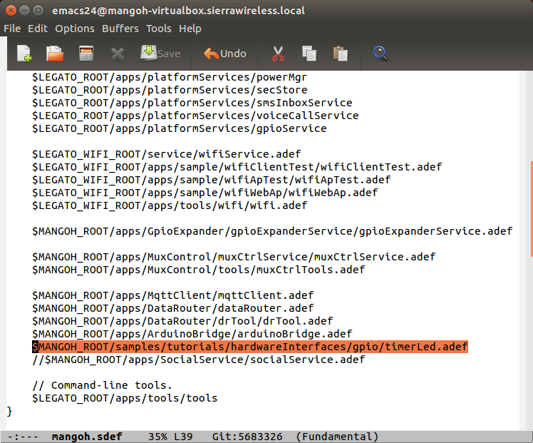
  1. Add timerLed.adef to mangoh.sdef
    1. Open emacs
    2. file->Open file
    3. mangOH->mangOH->mangoh.sdef
    4. Under “apps:{“ add “$MANGOH_ROOT/samples/tutorials/hardwareInterfaces/gpio/timerLed.adef”
    5. Save and close emacs
2016-11-09 21_07_34-Program Manager.png


  1. instlegato wp85 192.168.2.2
2016-11-09 23_27_47-mangOH Dev using Legato 16.07 on Ubuntu 16.04.1_1-Test [Running] - Oracle VM Vir.png

  1. cd mangOh/mangOH/samples/tutorials/hardwareInterfaces/gpio/TimerLed/
  2. mkapp -t wp85 timerLed.adef
2016-11-09 23_30_20-mangOH Dev using Legato 16.07 on Ubuntu 16.04.1_1-Test [Running] - Oracle VM Vir.png

  1. app install timerLed.wp85.update 192.168.2.2
2016-11-09 23_32_00-mangOH Dev using Legato 16.07 on Ubuntu 16.04.1_1-Test [Running] - Oracle VM Vir.png

  1. ssh root@192.168.2.2
  2. app status (should see “[stopped] timerLed”)
2016-11-09 23_18_10-mangOH Dev using Legato 16.07 on Ubuntu 16.04.1_1-Test [Running] - Oracle VM Vir.png

  1. app start timerLed
2016-11-09 23_20_48-mangOH Dev using Legato 16.07 on Ubuntu 16.04.1_1-Test [Running] - Oracle VM Vir.png

  1. You should now see the LED next to SW200 and the reset switch blinking

I have tested these steps out on a new install of the VM and have not encountered any issues. If you do have any issues or or have any comments regarding the process please share them in the comments below.

I would like to mention that the constant addition of new APIs for the mangOH board have made programing the board that much easier. As someone with a background in embedded code on microcontrollers, digging into the kernel to get to the GPIOs or other ports would be a quite a feat. The mangOH team is also working to add more demos, thi would allow someone wanting to create a prototype to have numerous starting points as well as projects that they could merge to get a usable prototype for the concept they are trying to display.

As I keep working with this board I will hopefully add more blogs giving over my experience with working with the mangOH Green board.


Wednesday, October 5, 2016

Home Automation Using the Sonoff TH & SV - Review

IMAG1240.jpg


Introduction

With home automation expanding faster than ever thought and new products constantly coming out the DIY space is increasingly getting bigger as well. One of those companies joining in the DIY space is Itead Studio. About 10 months ago Itead Studio came out with their Sonoff and Slamphor solutions and have quickly built on these two platforms.

Recently Itead Studio brought out two new home automation products that complement their current products. The Sonoff TH allows the user to automate a devices on/off control based on either temperature or humidity. The other product recently introduced is the Sonoff SV. This Sonoff works off DC voltages ranging from 5V - 24V.

The Sonoff TH was added to support common residential devices such as fans and  humidifiers. The Sonoff TH currently only allow the connected device to be switched based on either temperature or humidity, not both.

Hardware overview

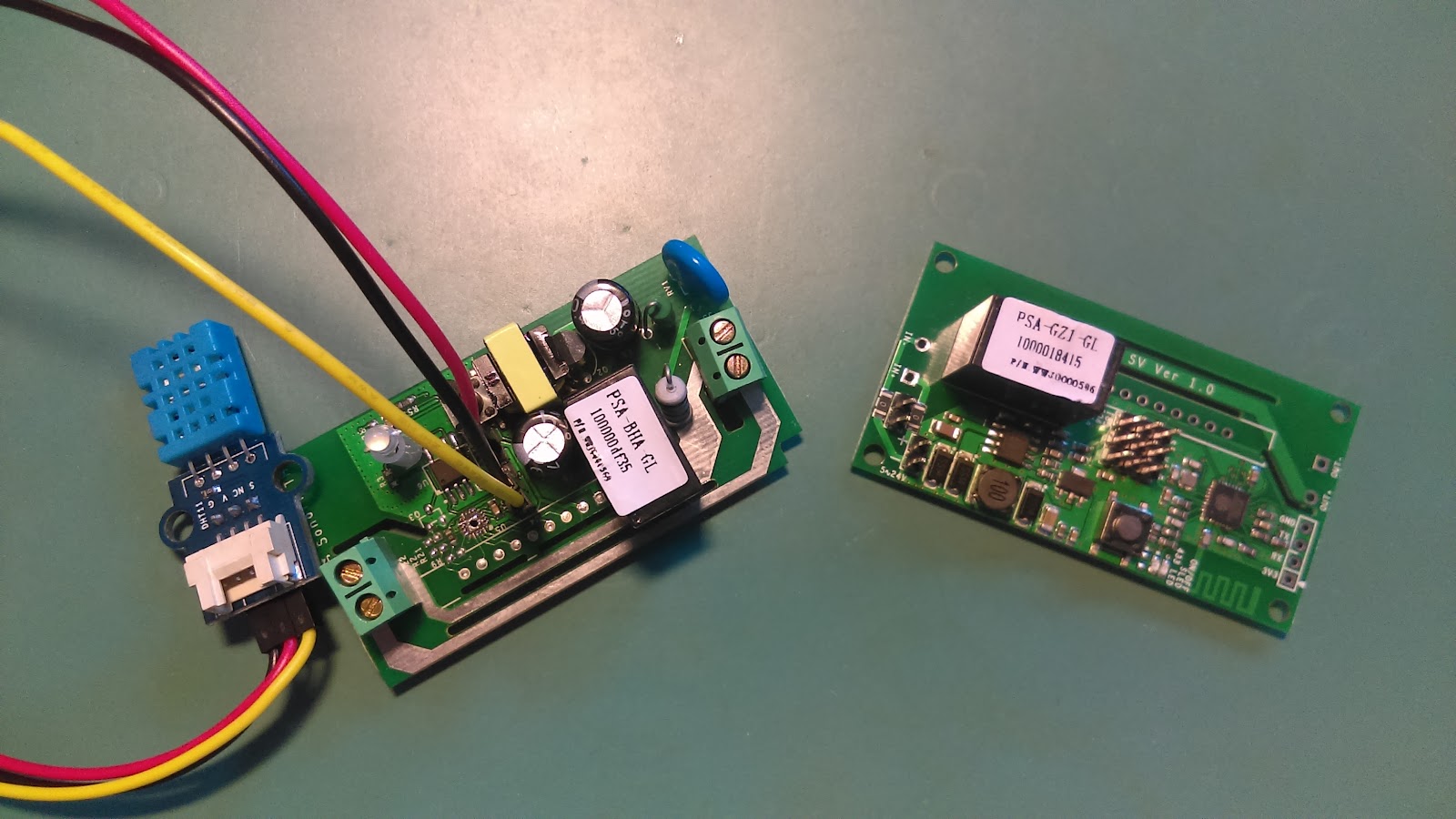
The Sonoff TH and SV internals have for the most part not changed very much from the original Sonoff. They still use a a 250V and 10A relay to do the switching on and off of the main power. The WiFi controller is the very popular and well used ESP8266EX. The onboard memory has been changed from Winbond to another company but I assume the general operation remains pretty much the same.

The main differences between the Sonoff TH and SV is in the power circuitry. With the TH needing to step down from 120V ~ 240V to 5V there is a transformer a bridge rectifier as well as other components to help stabilize and smooth out the incoming voltage. The Sonoff SV does not use mains voltage but rather uses 5V ~ 24V and as such only has a step down voltage regulator that outputs 3.3V to power the ESP8266.

It is interesting to note that both the TH and SV appear to have a location to connect the 433MHz RF module even if the code is missing to utilize them. Also the SV which should only operate 5v ~ 24V has the same track layout and spacing as the original Sonoff and TH.

Inline installation

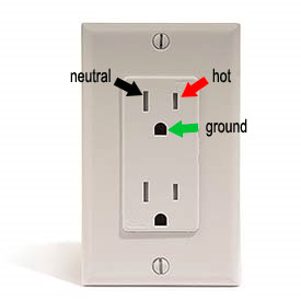
Setting up the Sonoff TH is relatively simple for anyone with basic knowledge of AC electricity. The most complex part is knowing which of the spliced wires in neutral and and which is live. A quick search will show that (at least for North American plugs) the large prong on the plug is neutral and the smaller one is live.

I say large and small prong because a decent number of home appliances use two unmarked conductors. This leaves the the only way to know which is neutral by looking at he connected plug. This leads to an ongoing issue with the Sonoff devices, lack of a third pin. With more devices including a ground connection, not having this connection leads to messy and possibly dangerous wiring. Currently the only workaround would be to leave the ground wire uncut and wire it around the outside of the Sonoff.

[000099]-001.jpg
Sonoff TH with only two connections, live and neutral

The Sonoff SV does not have this issue if used in the DC only mode. The Sonoff SV is a bit more involved in the connections however as there is no terminal block to easily connect wires too. The Sonoff SV needs the DC leads to be soldered directly to the board or terminal blocks added first.

[000136]-001.jpg
Sonoff SV without terminal blocks

Sonoff Setup

In a previous blog the steps needed to connect the Sonoff as well as connecting to the desired WiFi acces point were covered. This was mainly done due to a lack of clear instructions for those wishing to do so. Thankfully Itead Studio have updated their Wiki to not only include clear steps but GIFs showing what each LED setting means.

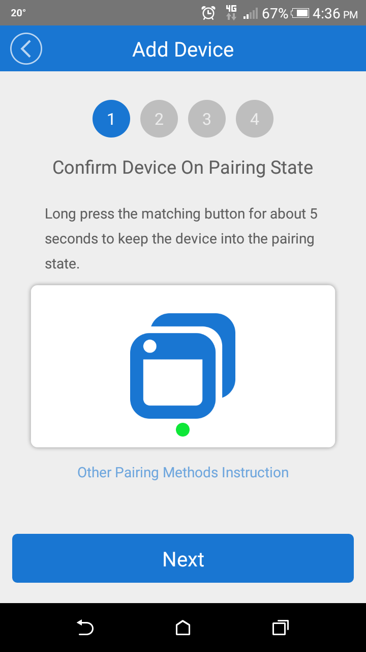
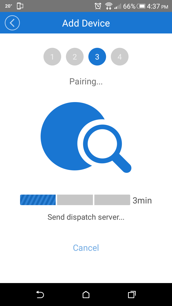
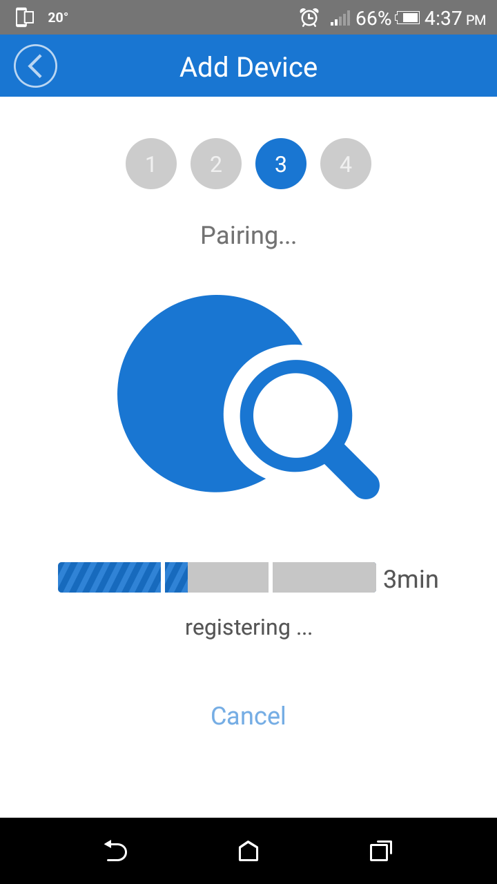
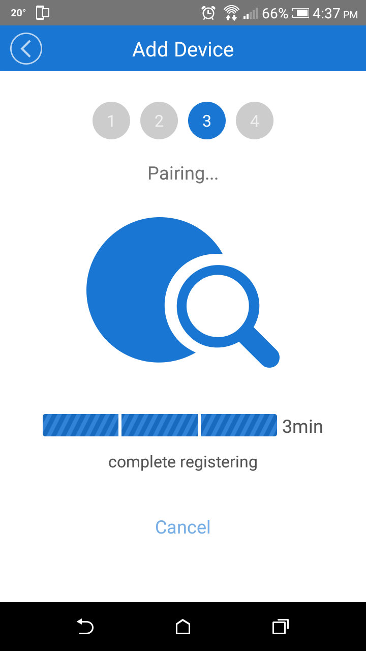
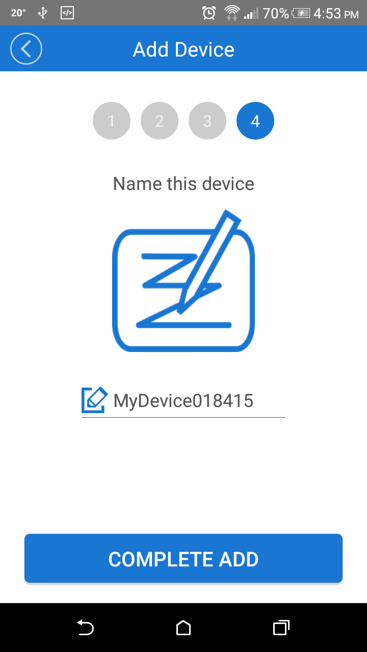
With the addition of these two new devices the pairing has become clearer. This was done by having the Android App take you through each step needed. You start by clicking the “+” at the bottom of the home screen to start the adding process. Once done the the app asks you to be sure the Sonoff is in pairing mode and shows you what the state of the LED should be. Then the app asks you to choose a WiFi access point and input the password for that access point. The app will then look for all devices in pairing mode and within range. Once the app has found the device, passed along the WiFi credentials and registered the device with your account you are asked to name the device. Once named and you have confirm that you have added the device correctly the Sonoff is ready to be used..

Screenshot_2016-09-22-17-15-34.pngScreenshot_2016-09-28-16-36-03.pngScreenshot_2016-09-28-16-36-08.pngScreenshot_2016-09-28-16-37-09.pngScreenshot_2016-09-28-16-37-41.pngScreenshot_2016-09-28-16-37-14.pngScreenshot_2016-09-28-16-37-50.pngScreenshot_2016-09-28-16-53-53.pngScreenshot_2016-09-28-16-54-27.png
The steps taken to setup the various Sonoff devices

This is a lot clearer and simpler than the previous suide steps provided with the previous versions of the app. The only issue that persists with the e-WeLink app is the way the password for the WiFi access point is handled. I had mentioned in my previous post about 10 months ago the issue with the WiFi password being stored in plain text. I also brought this up with my contact at Itead Studio and I was informed this would eventually be changed. But as can be seen this has not be taken care of as of this writing.

Connect to WIFI

The WiFi connection between the Sonoff and the router has so far posed no issues. I have tested a few scenarios of power outages and power cycling as well and so far have experienced no issues with the Sonoff not coming back online.

The explanation of the LEDs on the Wiki have definitely increased the understanding of what state the Sonoff is in. The LEDs have also reduced the number of questions regarding how well the Sonoff is working. Overall it feels that the reliability of the WiFi connection has been increased or at least maintained from the original Sonoffs to this newer version.

App Experience and Updates

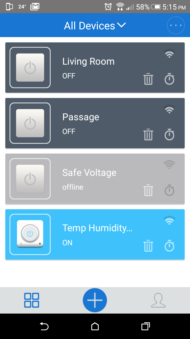
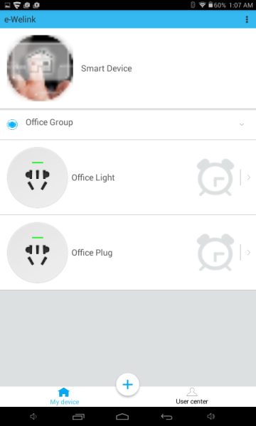
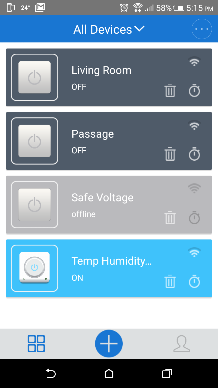
Itead Studio has also update the overall experience of the app and not just the device pairing portion. The interface is much cleaner and better organized. It is now possible to clearly see more than four or so devices in a single screen as well as the state of the device (on/off). Also updated is the ability to affect the state of manually controlled devices from the home screen. Previously one needed to tap into the device to change its state. With the newer app, this can be done by tapping the device symbol on the home screen. Also updated is the state notification. Previously there was simply a green “LED” to let know if the device wa son or not. This has now been changed to having the hole device row turn blue when on and grey when off. This makes it much clearer as to what the state of a device is at just a glance.

Screenshot_2015-12-03-01-07-14.pngScreenshot_2016-09-22-17-15-34.png
Old vs. New App

The Sonoff TH has another nice feature. When you tap into the device the current temperature and humidity reading are presented at the top. Not only does this allow you to know what the current conditions are in the area around the Sonoff TH but it also help you set the conditions for the Sonoff. By knowing the current conditions you determine if those conditions are what you want to change the state of the device or a slightly higher/lower setting be preferable.

Screenshot_2016-09-22-17-14-04.png
Sonoff TH Device Screen with Real Time Temperature and Humidity Data

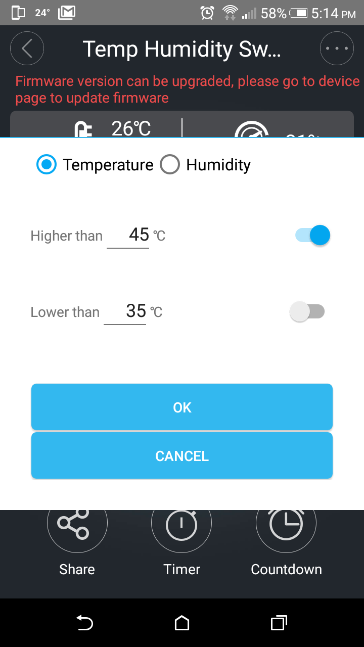
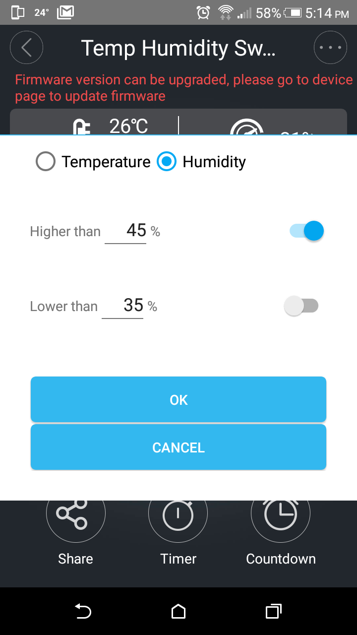
The setup of the Sonoff TH is pretty simple. After tapping into the device you are presented with the device settings. On this page you can change from manual to auto settings. . When you change from manual to auto a setup screen pops up. On this screen you can choose between temperature and humidity through two radial buttons. After selecting wich parameter to use you set the above and below values.  As an aside if the auto/manual button was bigger it would be easier to use. After tapping OK the device will act according to the setting selected.

Screenshot_2016-09-22-17-14-47.pngScreenshot_2016-09-22-17-14-51.png
Setting Threshold Temperature/Humidity Values

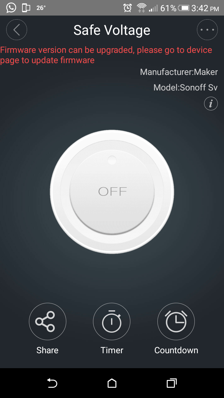
The Sonoff SV is simpler as it only has a manual on/off button. It should be noted that both of these devices also have a the timer as well as a countdown feature. The countdown feature allows you to set an amount of time after which the device will either turn on or off.

Screenshot_2016-09-22-15-42-53.png
Sonoff SV device screen

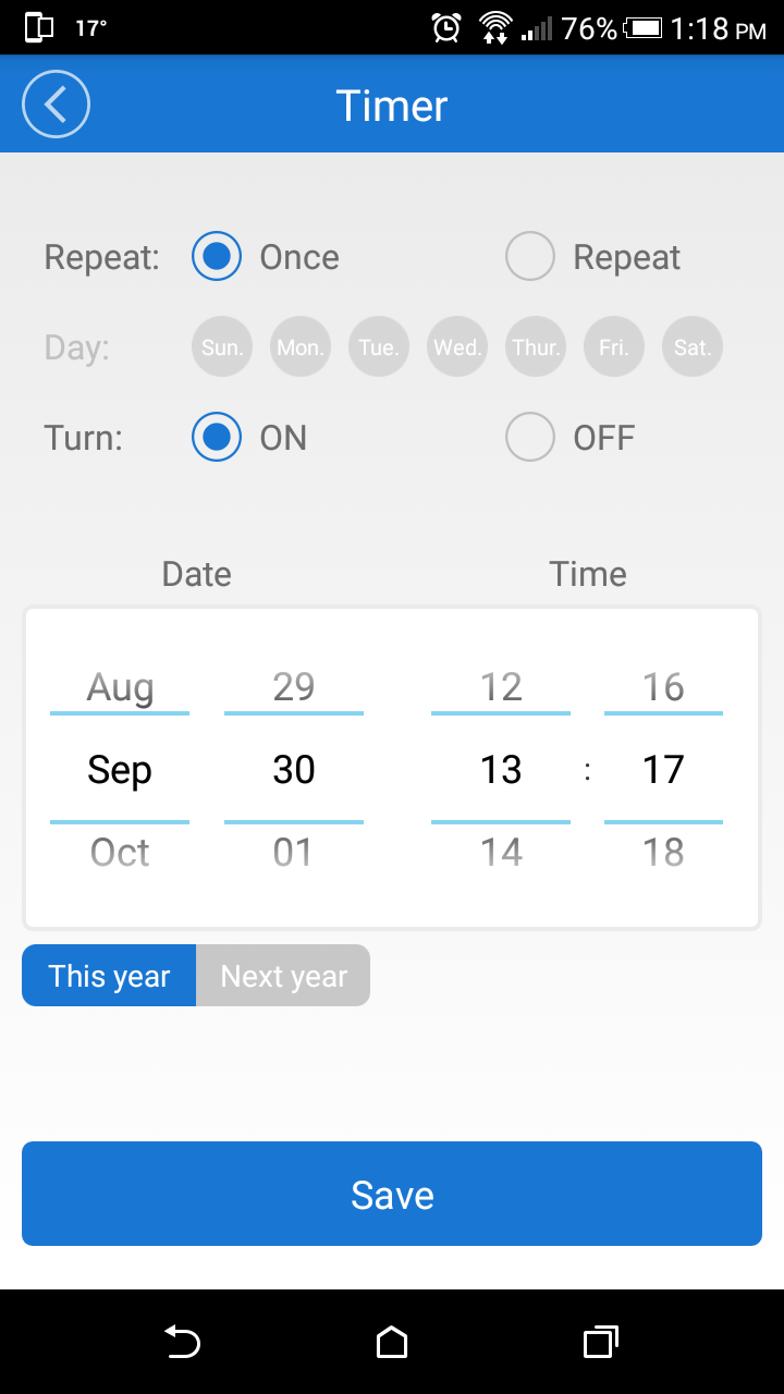
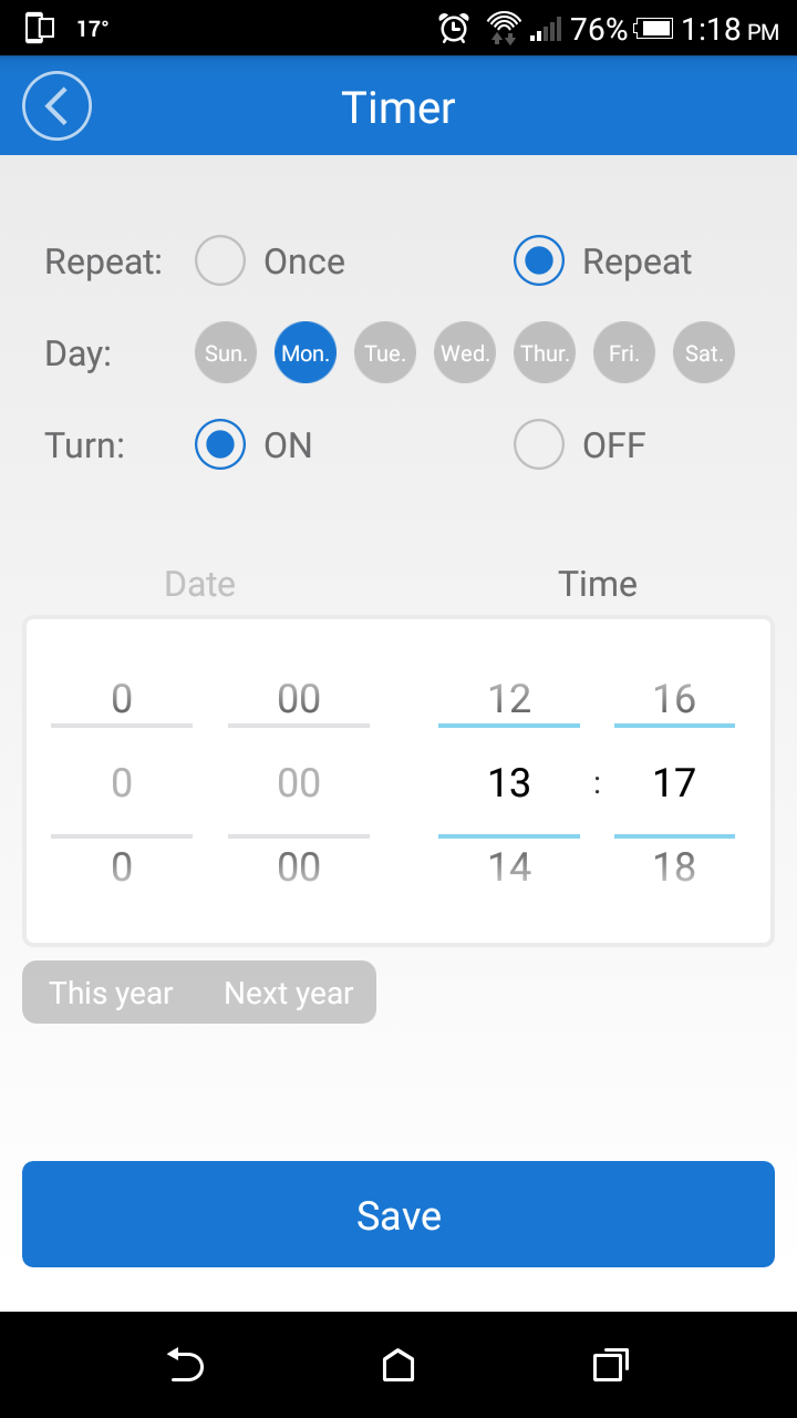
The timer function allows you to set up to eight different times at which you want the device to either turn on or turnoff. Considering a regular timer costs over $20 CAD this a big deal in itself. This is handy for someone leaving their house or wants something like a phone to charge for a specific amount of time.

Screenshot_2016-09-30-13-18-12.pngScreenshot_2016-09-30-13-18-17.png
Sonoff timer screen

There is one more overlooked setting on all the Sonoff devices, that is the power on state. This allows you to set the state the Sonoff when the device powers on. This is useful for power outages or other issues such as someone inadvertently unplugging the device. In this case you can set the device to be on/off on power up.

Screenshot_2016-09-30-13-17-05.png
Sonoff settings screen

A new feature with the updated app is something called Scenes and an extension of this called Smart Scenes. A scene allows you to group various devices and set the state as you wish. This means you can have a bedtime scene were your room lights turn off, your bedside lamp turns on etc.  Previously you could choose to have various devices all on or al off, this new Scene allows different states to be set for each device. An extension of this that is currently only available on the Sonoff TH, Sonoff, Sonoff RF, Sonoff SV and Smart Socket. In this Scene you can set the temperature above which the other devices should turn on. Hopefully this will be expanded in future iterations to not just have devices turn on but, also off as well as have different states change. If the addition of humidity control was also added the functionality would be completed for this extended Scene capability.

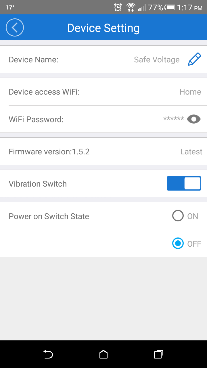
The only downside that with the app has already been mentioned. That is the way the WiFI password is handled. Hopefully after writing about this in two blogs Itead Studio will try find a fix so that the password, once entered, is not visible to anyone picking up your phone.

Power Consumption

Power consumption of both the Sonoff TH and the SV were attempted to be measured. This is relevant as these devices are meant to be left plugged in or connected to a power source at all times. The Sonoff TH was connected to a MCP39F511 from Microchip. This was used as it has decent reliability and I no longer have access to a PA1000.

[000280].jpg
MCP39F511 power measurement kit

The measurement from the MCP39F511 was between 0.4W ~ 0.67W. Comparing this with a previous measurement using the PA1000 for the original Sonoff shows the two are similar. The previous measurements appeared to average around ~0.54W but with the high and low ends in the same region.

The Sonoff SV was in the process of being setup to be measured when the unit stopped working. While the cause of this is unclear one thought may be the lack of reverse polarity protection. With no terminal blocks the connections are made either with older or by adding terminal locks. In my case neither were used instead breadboard wires were used. A miss connection may have lead to this issue.

Due to this I was unable to take power measurements for the Sonoff SV. If however it is the same regions as the original Sonoff this could cause an issue. With the SV presumably intending to be connected to a battery device, 0.5W could drain a sizable battery in just  matter or days if not hours. I would hope this to not be the case and hopefully I will be able to do these measurement in the future and update this blog as accordingly.

Concerns

The Sonoff have proven to be great group of devices that are both easy to use and install. They allow almost anyone to setup their own home automation system and to control their home in away they they see fit. There are however a few concerns. The first is with updates of the software on either an Android or Apple phone. I have repeatedly be asked to upgrade but not through Google Play. while some people might not think much about this, to me it poses a security breach that I prefer to not open.

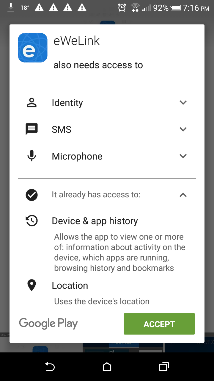
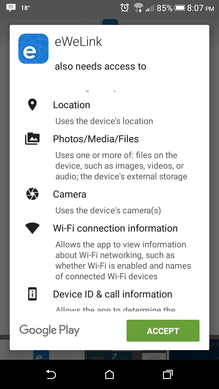
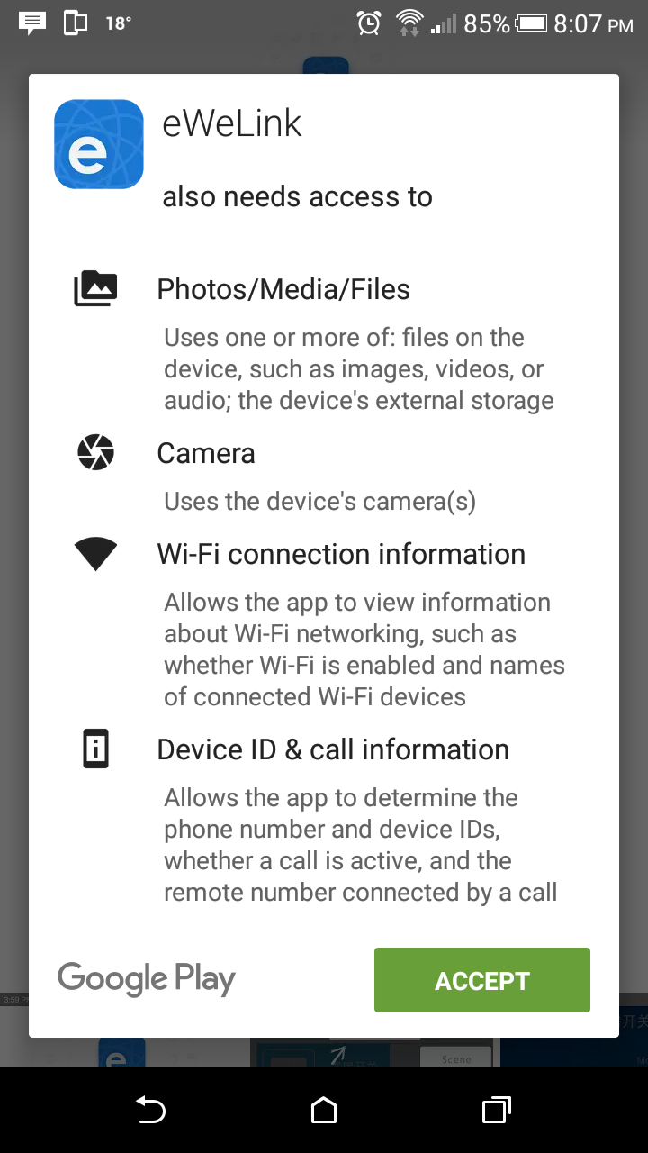
Another security concern is the accessibility the E-Welink app wants to the phone. Previously the app wanted access to the camera, WiFi information, Device ID etc. In the most recent upgrade the app wants access to the microphone, SMS and it it already has access to your location and call logs. Again some people may not think much about this but, such overreaching access to information in concerning and unwarranted. It should be noted I have NOT upgraded to the most recent firmware. I may rather find a new way to use devices that frees me of the constant monitoring by unknown and possibly untrusted parties.

Screenshot_2016-10-05-19-17-00.pngScreenshot_2016-10-05-20-07-47.pngScreenshot_2016-10-05-20-07-52.png
eWeLink “NEEDS” access to ALL these services....

Another security issue that has previously been mentioned but can not be stressed enough is the way the WiFi password is stored. Overall eWeLink has a lot of access to your phone and information. Unfortunately from what has been seen so far Itead Studio has not done much to secure this information or to show the user that this information is not being misused.

The another issue which has since been rectified for the Sonoff TH but not the Sonoff SV is the lack of cases. Without a reliable case the potential for an electric shock or shorting between conductors is always present. This presents a risk that a lot of people would not be willing to take if they young children or pets around.

Conclusion

Overall the Sonoff product line has been expanded in a useful way. These two products really allow for a wider number of devices to be connected to the IoT easily. While there are some things that Itead could improve with their app the overall experience is very good. The simplicity with which the Sonoffs can be installed really makes home automation something that anyone can do.

Thursday, June 23, 2016

SmartCharge 2.0: How to Install Uninterruptible Backup Lighting Cheaply and Efficiently

photo-original.jpg


Introduction

With extreme weather and power outages becoming more frequent, the need for a light that is not dependant on the grid is becoming increasingly important. Most people rely on flashlights or paraffin lamps for this but, this is often impractical and not always reliable such as when batteries are dead or when a light is needed immediately to prevent someone from getting injured.


The other option is emergency lighting but, this can be expensive, needs maintenance and is often fixed in place. Having it fixed in one location reduces its usability should a different area become higher priority.


For these reasons the SmartCharge 2.0 was introduced. The SmartCharge 2.0 allows any lamp to be used for emergency lighting should the power go out. Also with its innovative circuitry the SmartCharge 2.0 can be used just like a regular light even during a power outage.


Out of the box experience - Unboxing

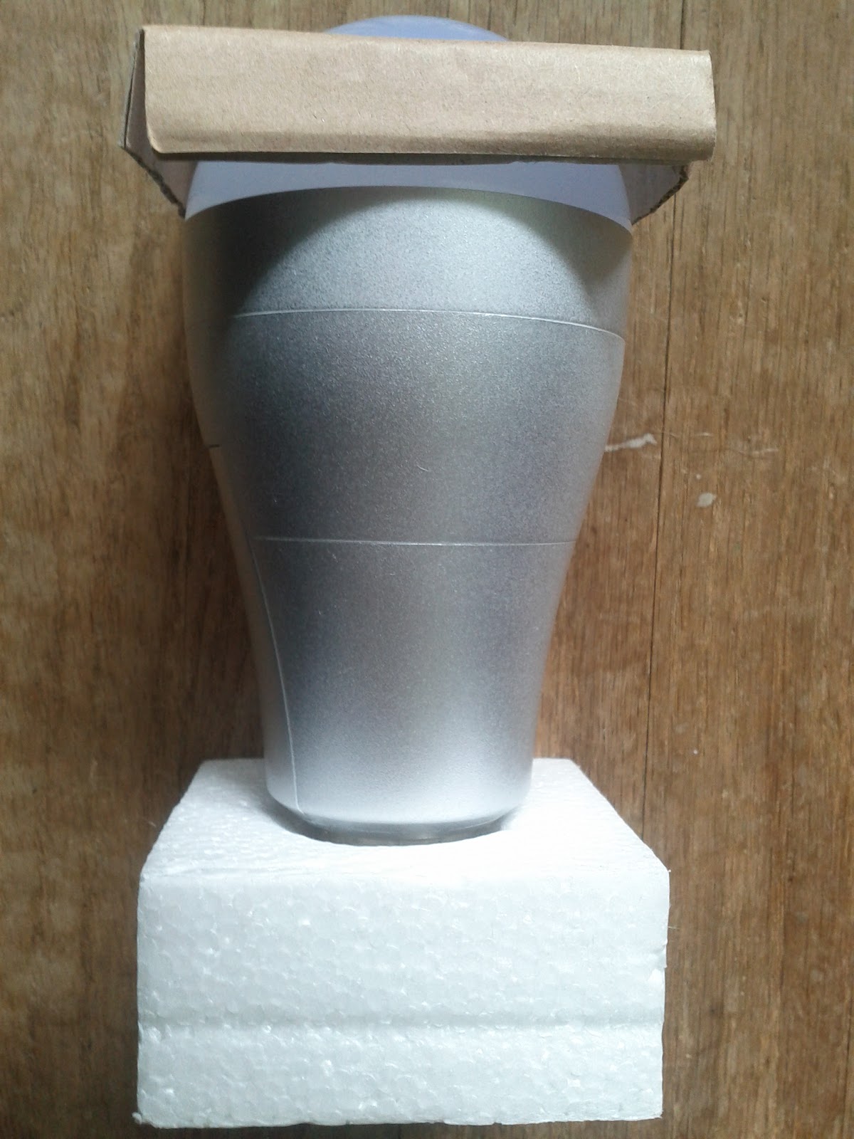
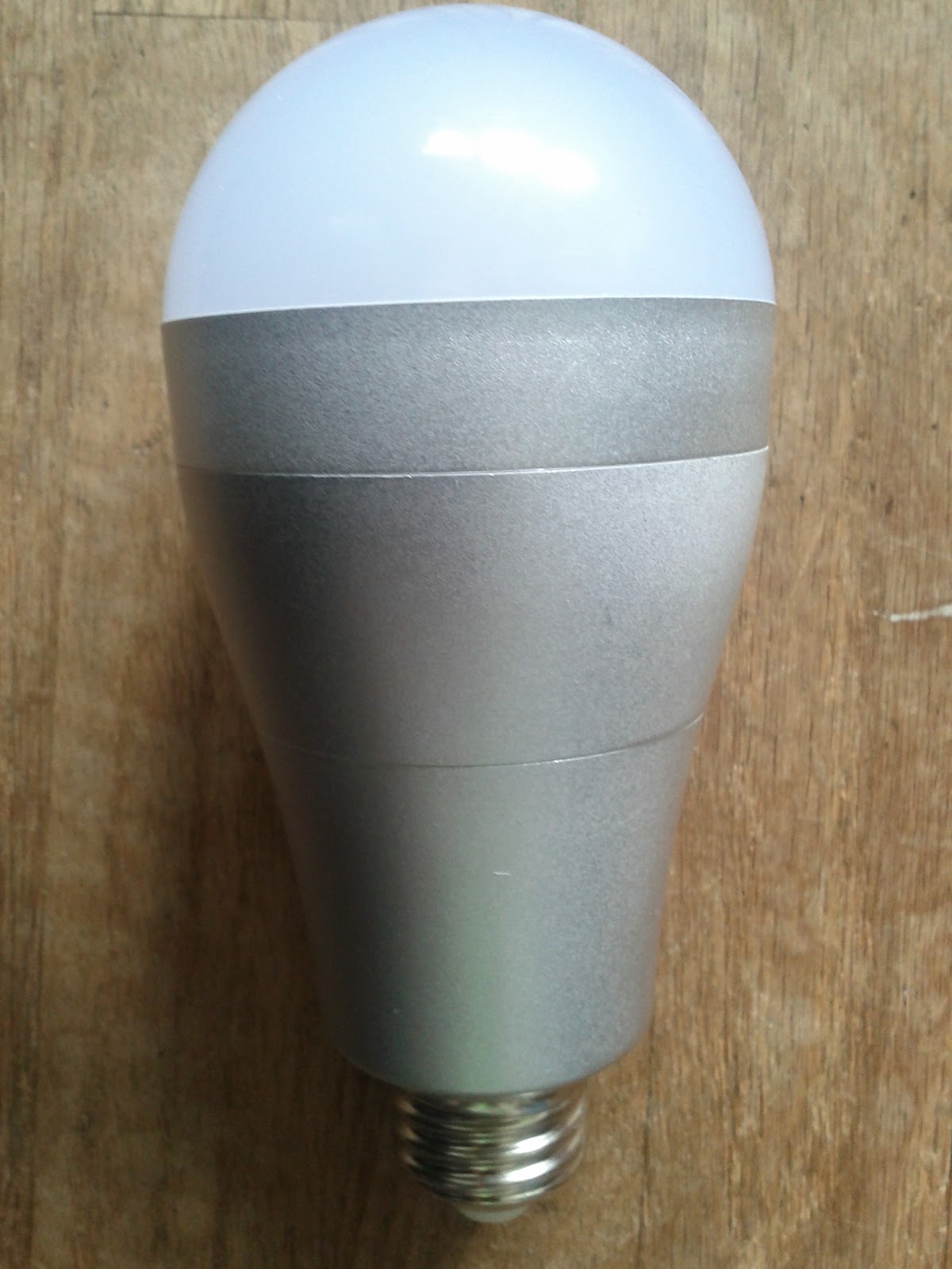
The SmartCharge 2.0 comes packed like a regular single LED bulb. While there are no markings on the bulb the SmartCharge 2.0 cannot be easily mistaken for another bulb. The SmartCharge 2.0 has a larger base as well as considerable weight over a regular bulb. Once out of the box installation is really as simple as screwing in a light bulb. While the bulb is larger than conventional bulbs, the SmartCharge 2.0 should still fit in most lamps and open light fixtures.


IMG_20160511_143411.jpgIMG_20160511_143501.jpgIMG_20160511_143519.jpg
SmartCharge bulb unboxing


Immediately after installation the bulb works as a regular LED bulb. In the same way a regular bulb turns on when needed so does the SmartCharge 2.0. The added feature of the SmartCharge 2.0 will kick in only after an extended period of charging. A full charge cycle, for an empty battery, is rated at 6 hours


There was a glitch noticed when using the SmartCharge 2.0 with some other devices. While the SmartCharge 2.0 is supposed to have a standard E27 base I had issues with two off the shelf products that I was attempting to use for testing.


Product feel and composition

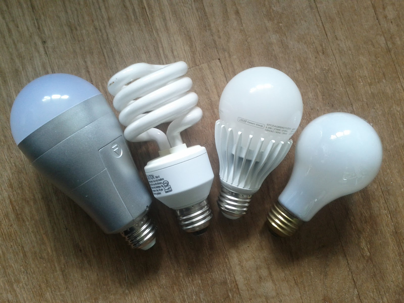
Immediately after taking the SmartCharge 2.0 out of the box you can tell that it is not a regular bulb. The SmartCharge 2.0 has both a different feel and weight. Compared to a regular LED or CFL bulb that has a shorter housing the SmartCharge has an extended housing and just a simple silver paint coating the bulb with no markings or ratings. This is a potential issue for someone using the bulb but has no prior knowledge what the bulb is or where it is from. A case would be in a house were a past tenant installed the bulb and forgot about it when moving out.


IMG_20160511_143636.jpg
SmartCharge bulb relative to other common bulbs


The weight of the bulb is another potential issue. Most lamps have the bulb mounted in a vertical position rendering the wight a non issue. But for other lamps or light fixtures that have the bulb horizontally at an angle this can be an issue. During testing the SmartCharge was placed in a floor lamp that allows the bulb to be rotated from the horizontal to almost vertical. Due to the weight of the bulb the lamp was often pointing horizontal or close to horizontal even though it started almost vertical.


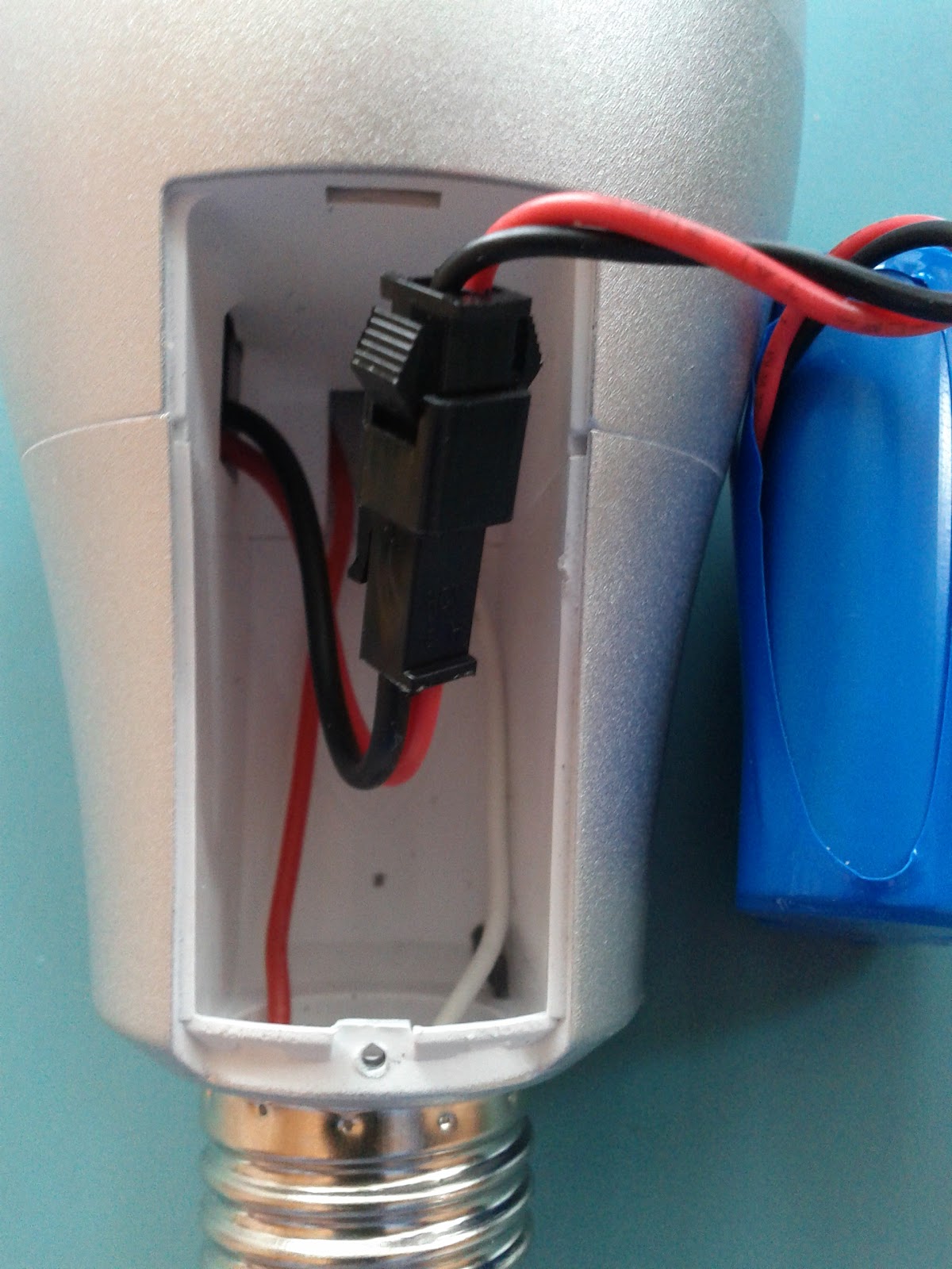
The battery housing is screwed in by a small philips screw. While this should almost never need to be opened the housing with the screw again is not done in an athletically pleasing manner causing the bulb to look out of place in any lamp that the housing is visible.


IMG_20160407_162318.jpgIMG_20160407_162411.jpg
Battery housing in the base of the SmartCharge


Power outages - simulated and real - usig breakers

As the SmartCharge is meant to be used in situations where the power abruptly shuts off, the bulb was tested as such. In order to test the bulb two methods were employed. The first method was that suggested by SmartCharge, connect a incandescent bulb or other resistive load in the same powerbar as the SmartCharge bulb with the power bar disconnected from the mains. The second method used was that of turning off breakers (removing fuses) in the breaker box right where power comes into the home. The reason for the second method was to verify the claim that almost all circuits in the home have a resistive load on them somewhere in there system.


Using the first method it was found that he SmartCharge worked with no issues. Using a 60W bulb allowed the SmartCharge to show off how it works when there is no mains power but there is a load. It was also discovered that no load is needed, just an electrical path between the two connection points of the SmartCharge bulb. For this even a short circuit would do and it did quite surprisingly without damaging the bulb.


How the SmartCharge 2.0 Works

The idea behind the SmartCharge is pretty smart and interesting. It should be noted this is all from black box testing as the SmartCharge bulb could not be opened without causing severe damage. The SmartCharge puts out a small signal, whether this is AC or DC could not easily be determined. But from some basic testing it appears to be a 3.5V DC signal. This signal if returned (i.e. there is a complete electrical path) turns on the bulb if not the bulb remains off.


It is for this reason a load is need on the same circuit as the SmartCharge bulb. The bulb needs a complete circuit to work. If there is no load there will not be an alternative path to complete the circuit and to turn on the bulb. This brings us to the need to have the SmartCharge bulb in a place that it will be in frequent use or the bulb will not work when needed.


Battery - Usage, Length of Time, Not charged issues

The power behind the SmartCharge is a 7.5V and 1500 mAh Li-Ion battery in the base of the bulb. During operation in battery mode the bulb will flash when there is approximately 15 minutes remaining. In the testing conducted it was found that the run time is in the order of 3:20 - 3:35 before the bulb gave a low battery indication. This is inline with the manufactures spec of 3.5 hours, while this does not give any leeway or wiggle room for their claims it is accurate. The surprise came in the warning time. Instead of having 15 minutes as expected before the bulb when dark, it was closer to 30 minutes. This definitely would allow those in need the extra time to prepare before losing a last source of light.  


The drawback to the method used to turn on the bulb, as explained above, is that the bulb is always consuming power. The issue with this is it does not apear to be a small amount of power. If the bulb is left unused for a period, a day or so, there is a noticeable depreciation in the bulbs run time. This leads to the question of what is the true power consumption of the SmartCharge.


Power Consumption in charge mode

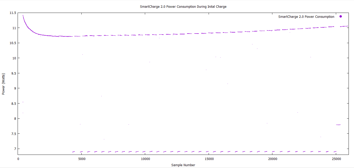
The SmartCharge 2.0 claims to be a 8W LED bulb. While most bulbs claim a wattage they often come in under their rated value even if just slightly. Since the SmartCharge list one of its benefits as Eco friendly this was a something that needed verification. Thankfully Tektronix generously lent me a PA1000 for just such tests. What was immediately evident was the higher than claimed power consumption of the SmartCharge. While not consuming as much as an incandescent of CFL the SmartCharge was 37.5% over its rated wattage.


SmartCharge 2.0 Power Consumption During Initial Charge - 1.png
SmartCharge charging over a 7 hour period with the bulb on


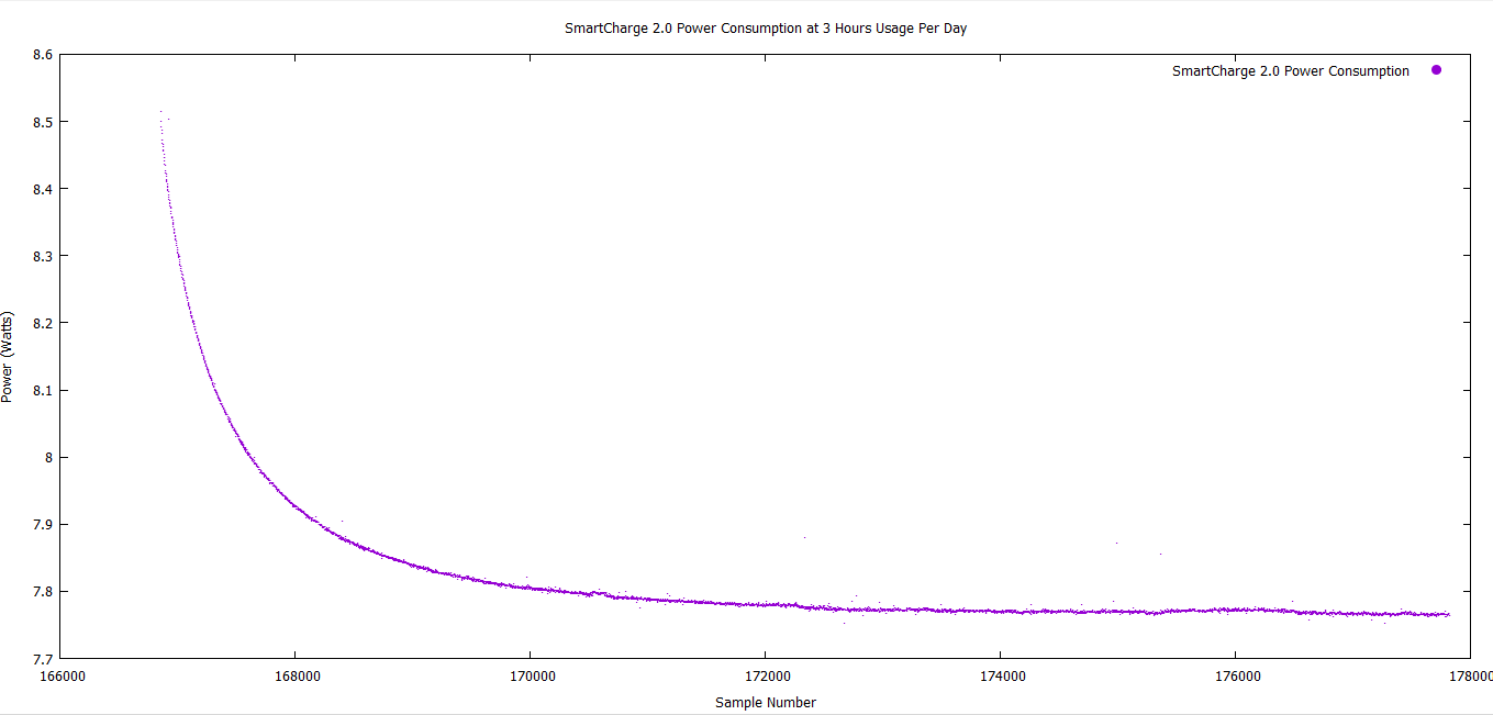
While SmartCharge would clarify that this value includes the charge power of the battery, that is part of the bulb, also the battery is always looking to remain fully charged. In one test the bulb was left off for a number of hours. When the bulb was turned back on the battery was again being charged. This leads to the conclusion that unless the SmartCharge is in constant use, with no multi hour breaks, the battery will be repeatedly charged.


SmartCharge 2.0 Power Consumption for 3 hours usage.png
SmartCharge power consumption over 3 hours after being off for 21 hours


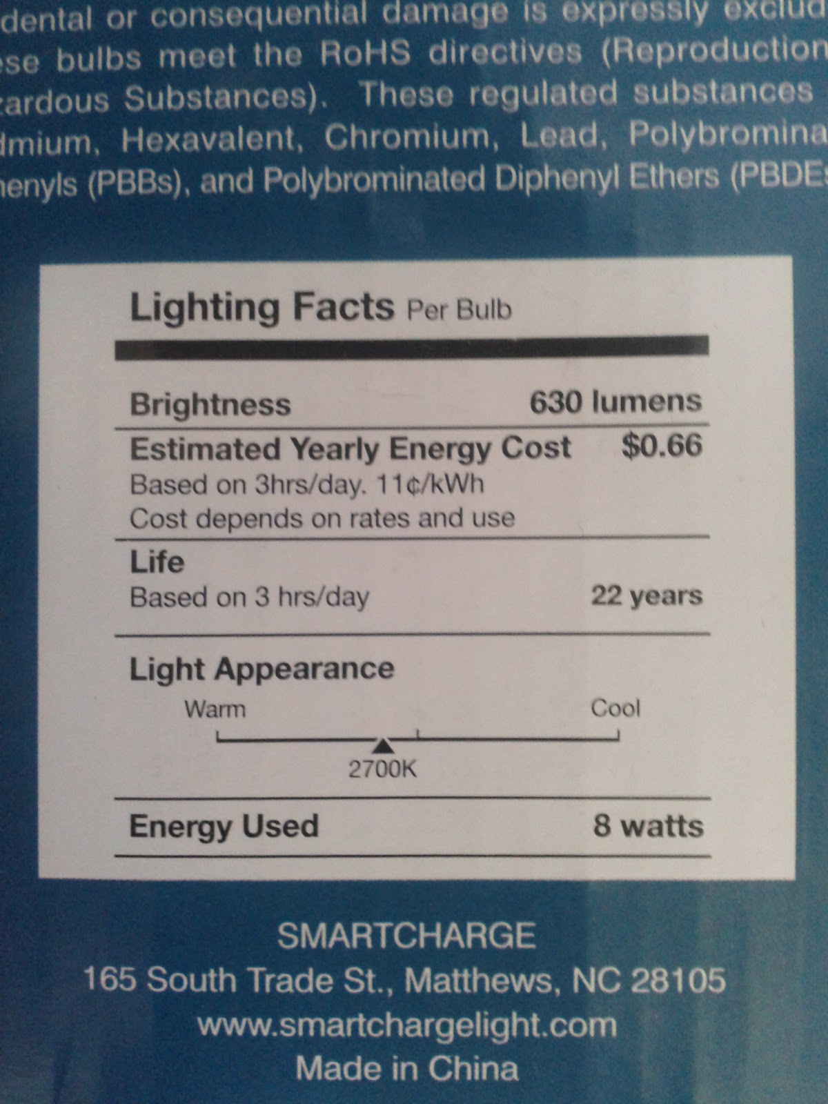
The SmartCharge box claims $0.66/year to run the bulb at 3 hours a day, this is however very misleading. If only the 8 watts for those 3 hours a day are used in the calculation then we get:


365(days in a year) x 3(hours on per day) = 1095(hours on per year)
1095(hours on per year) x 8(watts consumed by the bulb) = 8760 Wh per year
8.760 (kWh per year) x $0.11(cost per kilowatt hour) = $0.96


IMG_20160506_134514.jpg
Power consumption claims on the side of the box


While this may not seem like a to wild exaggeration $0.30 is 45% over the claimed cost of only $0.66 per year, but this is still a very conservative estimate. If we look at the more realistic power consumption when using the bulb for only 3 hours a day and the need to constantly charge the battery the numbers get worse. With these calculations we can only wonder how SmartCharge was able to claim an estimated yearly energy cost of only $0.66 per year.
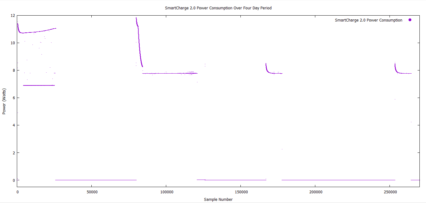

SmartCharge 2.0 Power Consumption Over Four Day Period.png

SmartCharge power consumption over a four day period (3hrs/day)


Reliability - Safety issues

From a purely reliability point of view the SmartCharge has taken a large step in the right direction. During all tests to simulate a power outage there was no interruption of light nor was it even a noticeable that the power had been cut.


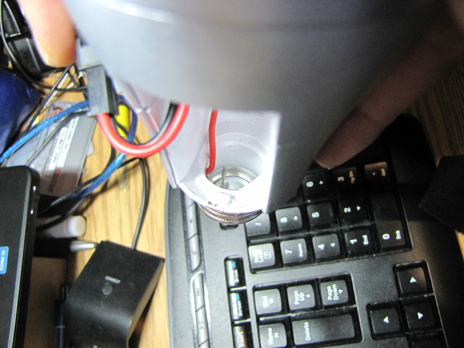
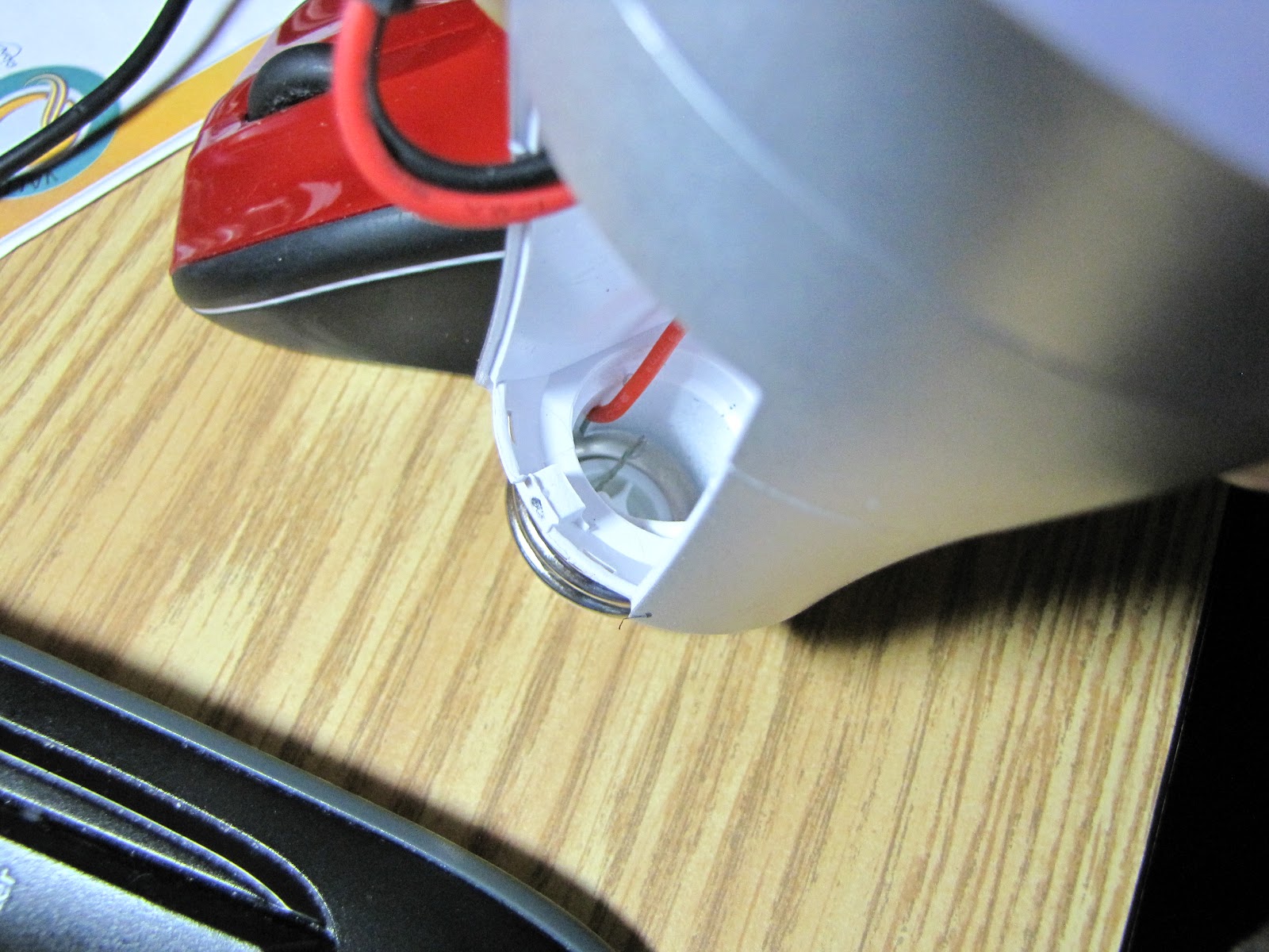
However there was an issue that was noticed with the sample I was given to review. There was a long unsheathed connecting wire in the base of the bulb. This wire is clearly long enough to allow the two terminals in the bulb to touch, shorting the mains power. This should not be an issue in a home with functioning breakers or fuses installed, but relying on safety equipment instead of designing with safety in mind from the beginning is not good engineering.


IMG_0680.JPGIMG_0688.JPG
Exposed mains wire in the base of the SmartCharge


I did mention this to the SmartCharge team and I did not feel the issue was taken very seriously. While I was assured this was an issue found in only a very few of the bulb on the production line this was not quantified in any way. I was assured this issue was mentioned to the manufacturer and corrective measures would be taken to ensure this does not happen in future.


Conclusion - Pros and cons

In conclusion the SmartCharge 2.0 is an interesting and innovative solution to an increasingly common problem. The easy of use and the simplicity of installation make this a truly foolproof product.


That being said at this point there are some issues with the product that need to be addressed before I would buy into such a product on a large scale. Firstly is the true power consumption. While the LED part of the bulb may be rated at 8 Watts the true consumption is above this. The cost of energy consumption calculation put out by the manufacturer is both false and misleading.
Second is the constant charging of the battery. If the battery is 90% full there may not be a need to charge it again and again. Maybe rate the bulb for 3 hours operation and then if the bulb is only 90% full you will still get the rated number of hours.  
Thirdly is the standby power consumption of the battery. If the bulb is not used for a day or two I should not find that the battery is in a considerable state of discharge. The manufacturer may want to look at a way to decrease this standby power consumption. This would give an overall better product, both in power consumption (closer to the rated 8 Watts) and longer standby times (battery not discharging in a few short days).


Lastly is the safety issue. If SmartCharge can clearly show that the bare wire in the base of the bulb was taken seriously and is no longer an issue. As well as that the UL compliance rating is followed correctly then I would look at the SmartCharge 2.0 as a truly viable and worthwhile product. If SmartCharge does come back with other information regarding any of my issues, I will gladly update this blog entry.