Friday, December 5, 2014

Sudden Impact Challenge - Blog Entry 1


I would like to say a big thank you to Element14 for hosting this challenge. I would also like to say thank you to the supporters, Analog Devices, Tektronix, Electrolube and Leeds Becket University for selecting my proposal and giving me the opportunity to take this idea further.

Project Outline
This objective of this project is to monitor an athlete to determine if any critical harm may have occurred or will have the potential to occur. The technologies that will be incorporated are as follows.

  • Temperature sensor -  to look for heat stroke or other temperature related issues
  • 2 or 3 Accelerometers - concussion sensing using sensor fusion
  • ECG front end - for potential or occurring heart attack detection
  • ECG front end - Detect sudden heart rate increase that could be potentially harmful
  • Wi-Fi/Bluetooth - to relay information back to a monitoring station

The exception of the system is to have a battery life of 1 ~ 2 years and to be self contained in a sports helmet (hockey, football or bicycle). If some components are not possible to incorporate directly into the helmet a chest strap may be added that will communicate wirelessly with the rest of the unit.

Deliverables
To keep the project at an achievable level the deliverables I propose will be inline with what I hope to be able to achieve in 3 months. While this list is somewhat smaller than the initial proposal, it will still deliver a decent overview of the athlete and will also provide a platform for potential future development.

  • Heat stroke will be fully implemented looking for abnormal body temperatures.
  • Heart attack will be implemented on a simple level; this would be only looking at abnormally high heart rate or abnormally high climb in heart rate. There is the potential to look for an abnormal heart rhythm time permitting. However, learning the athletes unique heart rhythm will most likely not be a possibility due to time constraints and potential complexity in doing such.
  • Individual concussion severity will be fully implemented and have a high degree of accuracy this should use some form of filtering to ensure only actual concussions are registered and measured
  • Cumulative concussion force may not be fully or correctly implemented. As it is still not fully clear in the scientific community how this should be measured, my attempts to do so may appear flimsy and illogical. While there may be an attempt at this it may be incorrect and inaccurate and therefore left out in the final product.
  • Monitoring and reporting, for this the CC3100 in conjunction with a MSP430F5529 or similar will be used to post the data to a cloud based system such as Plot.ly to give real time information on the athletes sensor measurements.

Next Steps
The immediate next steps is to better understand the proposed devices to be used. This includes reading through and understanding the data sheets and mapping what each component needs in the way of power (3.3V or some other value) communication (I2C, SPI, etc.) and what its limitations are in terms of performance and usability (FIFO, interrupt driven, etc)

At this point there is no plan for any software implementation or outline as there needs to be a better understanding of the individual components and what each one needs and is capable of. There is however an intention to layout a data flow and processing diagram in the coming steps to better help the layout of the hardware and the outline of the software.


Data Sheets
For convenience I have linked the data sheets for the proposed components to be used, as more components are added their data sheets may be added below.

  • ADuCM350, 16-Bit Precision, Low Power Meter On A Chip with Cortex-M3 and  Connectivity (link)
  • AD8232, Heart Rate Monitor Front End (link)
  • ADT7320, ±0.25°C Accurate, 16-Bit Digital SPI Temperature Sensor (link)
  • ADXL375, 3-Axis, ±200 g Digital MEMS Accelerometer (link)
  • ADXL377, Small, Low Power, 3-Axis ±200 g Accelerometer (link)
  • ADXL362, Micropower, 3-Axis, ±2 g/±4 g/±8 g Digital Output MEMS Accelerometer (link)


Original post on Element14 can be found here

Wednesday, December 3, 2014

Sudden Impact Wearables Design Challenge - Application

Prelude
Concussion traumatic brain injuries and other serious athletic health issues have taken center stage in recent years due to both new research and injuries sustained by professional athletes. This new research has shown that not only is a single concussion a potential health issue but also that concussion related damage is cumulative.
There are a lot of fitness trackers on the market that athletes are using but these trackers pose several issues. Firstly most of these trackers are for fitness only and therefore are not looking at health related issues but rather how an athlete is performing over time and how they can better perform. Another issue is the individuality of such fitness trackers, these trackers are made for an individual to track their progress and therefore multiple units cannot easily be viewed by one person such as a team coach. For the trackers that are viewable by multiple people, there is often a time delay in reading the acquired data making the data un-useful in real time athlete monitoring. Lastly most if not all fitness trackers have no way of looking at things such as concussion severity, cumulative concussion damage or imminent heart attack risk.
Reason for application
My reason for applying to this challenge is largely due to my interest in sensor related technologies and the ability to integrate different sensors data to be able to help people in everyday life. With the number of emergency room visits due to sports related injuries increasing each year there needs to away to better assess the degree of these injuries are and what their long term effects are.
Going beyond the sports fields, these same technologies can be useful in older patients who may suffer similar injuries in their daily lives as an athlete on involved in a contact sport may. Therefore with the percentage of the population above 65 increasing to the point that they they will soon become the dominant demographic, we will need away to be able to care for them without the 24 hour care of a care facility or live in help.
Since it is often easier to start with a willing customer as well as a large customer base, starting in the sports arena is an obvious beginning when looking at monitoring the vital signs as well as extent of injury in a person.
My Proposal
A sports helmet that monitors an athlete's body temperature, heart rate and rhythm as well as head trauma would be implemented to read and transmit these measurements back to a command post. There would be the possibility of adding an oxygen sensor by the athlete's mouth or nose to monitor their O2 intake.
The health related issues I would like to tackle with this setup is the immediate health risks an athlete may face while involved in the sport. These health risks would include heat stroke, sudden heart attack and seriousness of individual concussion as well as long term cumulative concussion force sustained by the athlete.
These risks will each be monitored by an individual or group of sensors. An outline of how each symptom will be monitored as well as how it will be diagnosed will follow.
Heat Stroke
By placing a temperature sensor on or close to the temple the body's internal temperature can be monitored. This is true due to the location of the temporal artery that is located below the temple. As the temporal artery is a major artery the temperature of the blood it carries is very highly representative of the body’s internal temperature.
With the use of an accurate temperature sensor (ADT7320FBZ ) it would be possible to determine if the athletes internal temperature is reaching a dangerous level and should be removed from the sport to cool down or if other urgent actions should be taken to reduce any health risks to the athlete.
Heart Attack
Using the ear or potentially other parts of the head, it may be possible to monitor the rhythm and electrical signals of the heart. These signals can be checked against a baseline rhythm to determine if any abnormalities are present. These abnormalities may indicate an impending heart attack, over exertion or other potential medical risks. If the system is used constantly by the same athlete it would be possible to have the system learn the individual's unique rhythm over time and then indicate when the rhythm is no longer in the normal rage. The same could be applied to the heart rate, if an athlete’s heart rate increases either at a dangerous rate or increases above a safe threshold again this could be reported to someone monitoring the athlete.
The athlete's heart signals could be monitored using an ECG front end chip (AD8232 HRM FRONT END). The signals could then be passed to a uC to do signal analysis and potently signal matching to determine if the rhythm is no longer normal. The signals could also be passed through some form of learning algorithms to help predict abnormalities. In the case of any such abnormalities being detected it would then be a simple matter to alert someone for urgent medical help.
Individual Concussion Severity
As the head is the limb most at risk due to blunt force trauma, this would be the center of the health monitoring system. With the use of two or more 3-axis accelerometers it would be possible to reasonably accurately measure the force sustained by an impact to the head. This would be an important and extremely useful bit of information in determining if an athlete should continue in the sport or be pulled to prevent further injury. In the event of a severe injury were an athlete would not be able to continue playing the information would help doctors to better understand the nature and extent of the injury sustained.
The use of two or more accelerometers (ADXL375, ADXL377, ADXL362) would be used to determine the extent of the force as well as what type of force was sustained in the head trauma. Further to this it may be possible and even useful to incorporate a gyroscope to help determine if there was a high rate of rotational force that may have caused a neck injury and to what extent this injury has occurred.
Cumulative Concussion Force
Besides the risk of an individual blow to the head, there is a real and more recently known threat of long term cumulative head trauma. As this is still something being looked into the method of reporting this is not currently clear. One method may be to use a running average to determine the average force sustained by the athlete’s brain. Another method may be some form of average but were higher and potently more recent traumas hold a higher influence of the final value. More research into this would need to be conducted to make this value a usable and meaningful number.
Monitoring and Reporting
The data obtained by the onboard sensors would be relayed to a coach’s Wi-Fi or Bluetooth enabled laptop for real time updates. There would also be alerts for urgent warning such as heart abnormalities or extreme heat trauma or body temperatures.
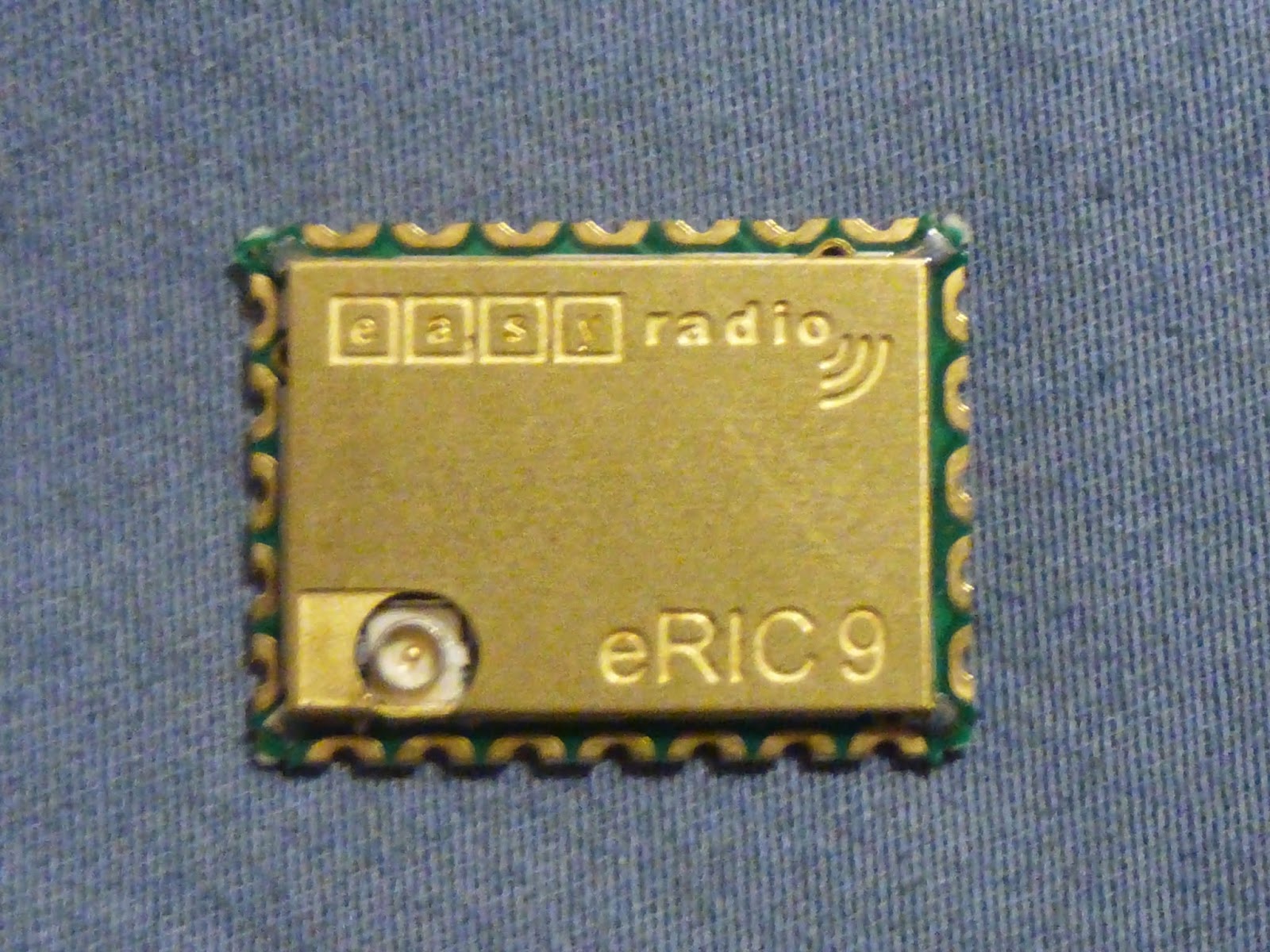
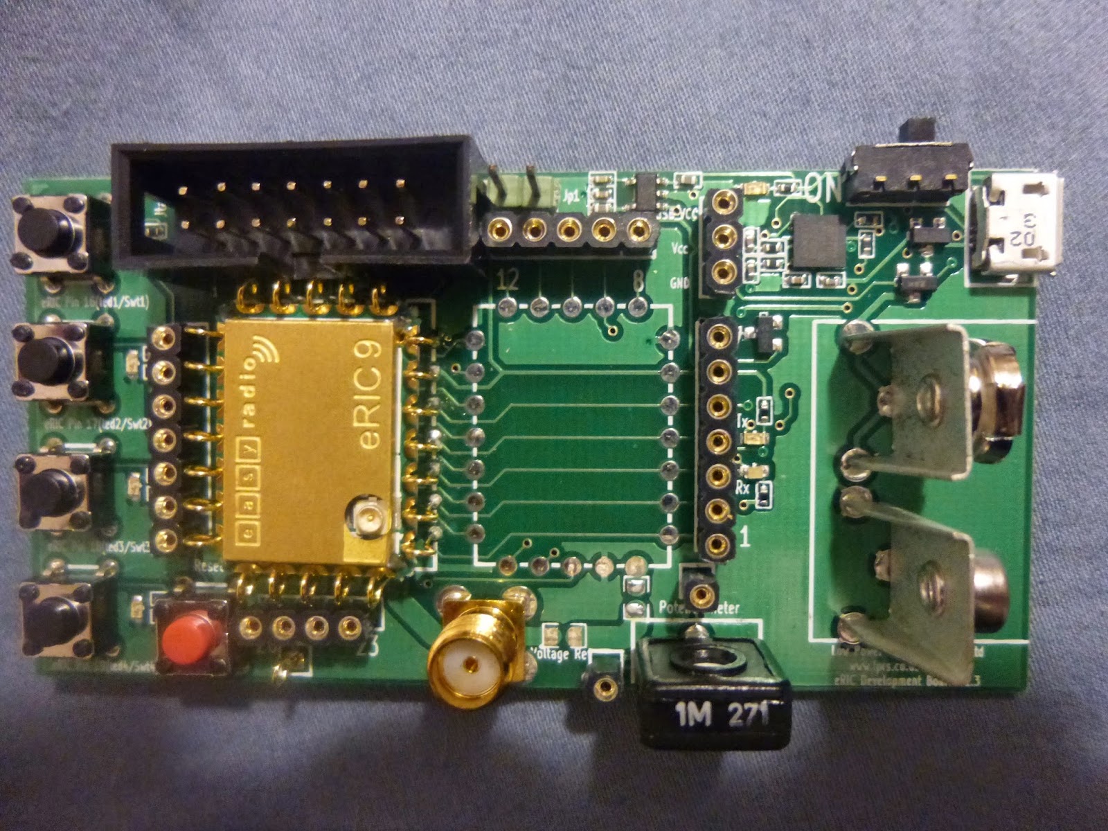
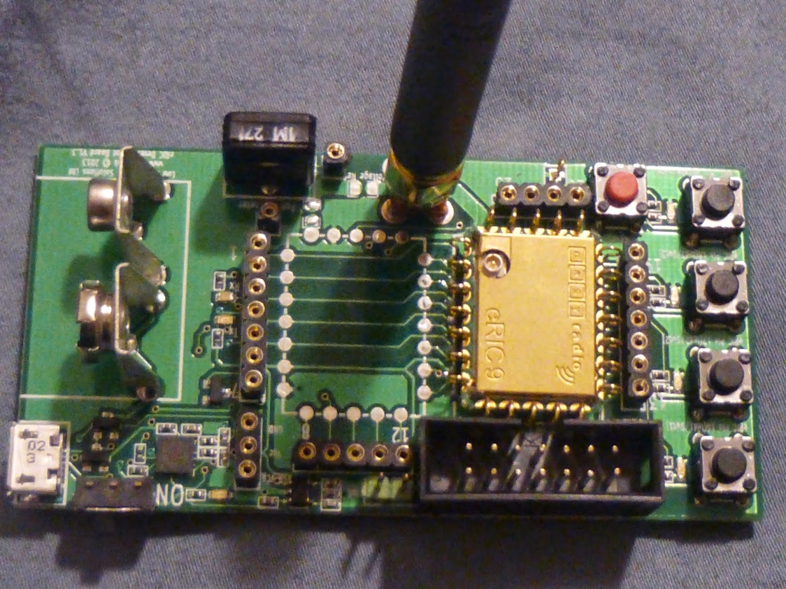
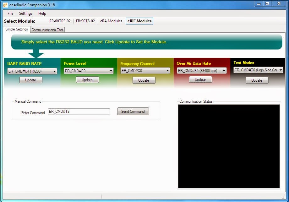
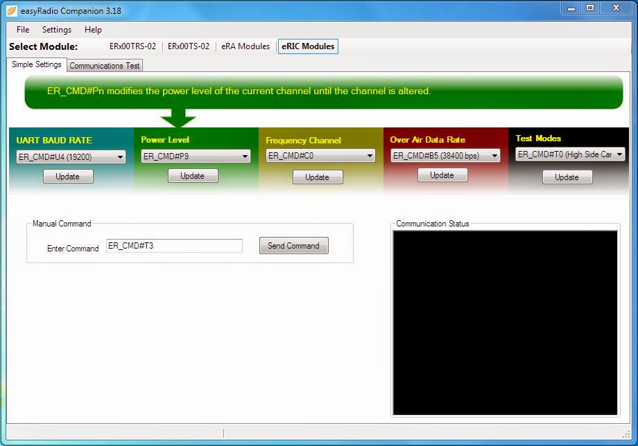
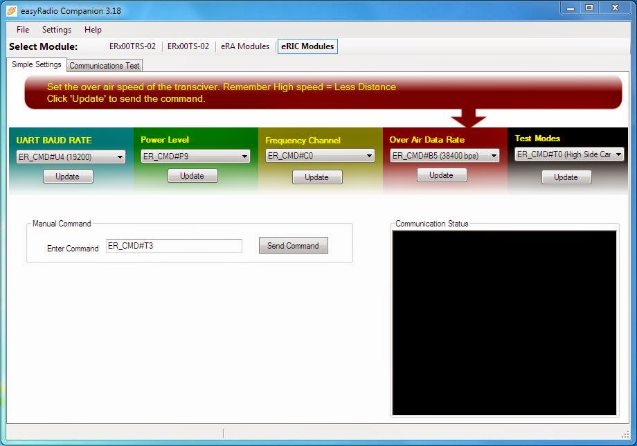
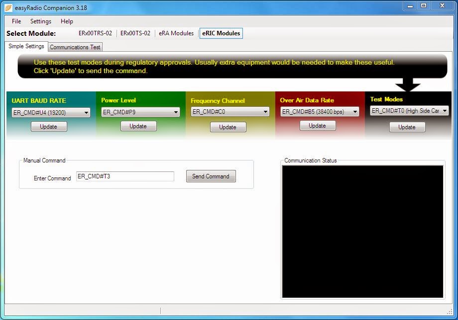
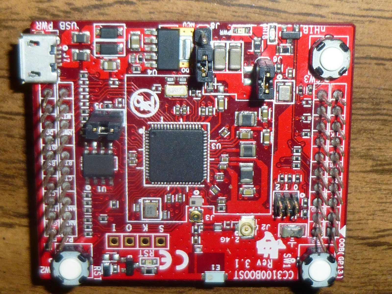
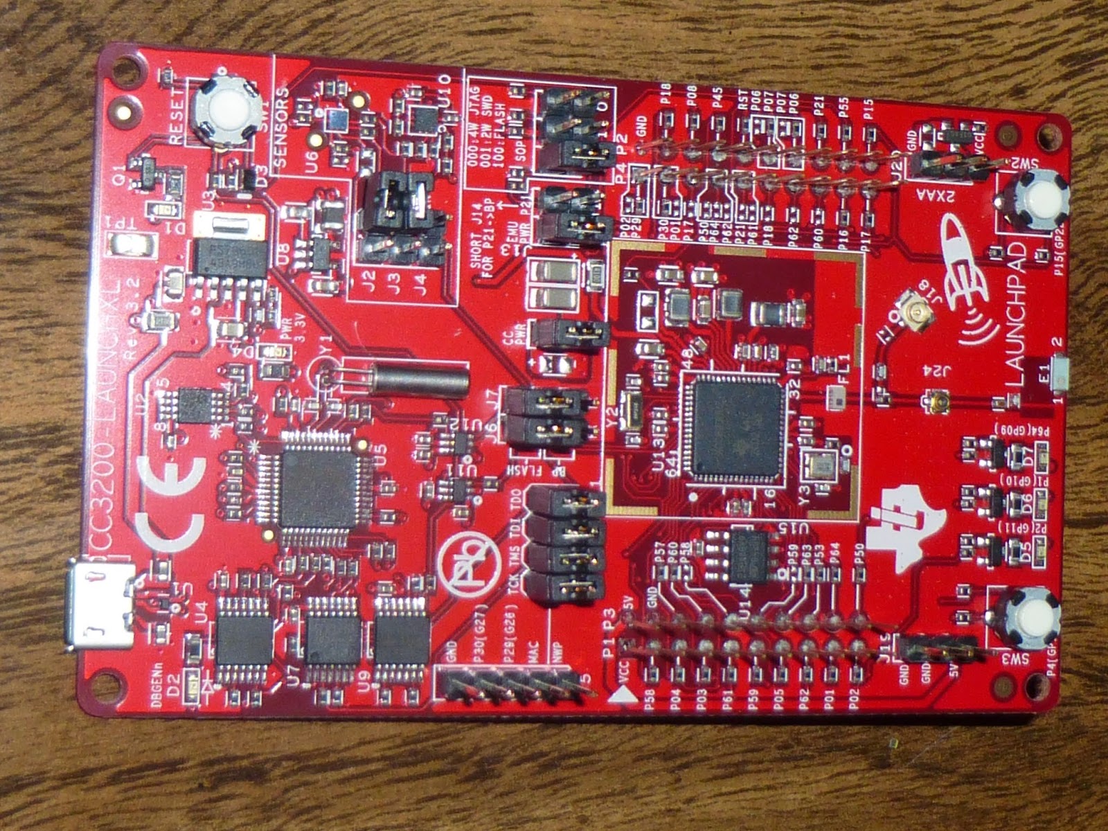
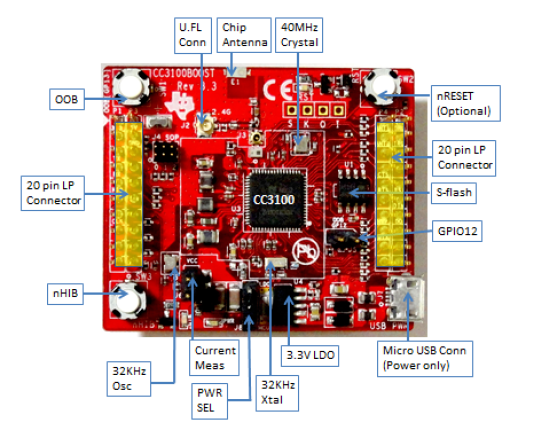
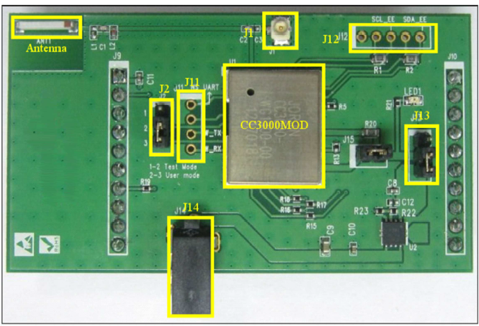
This data would be transmitted using an Anaren Air Bluetooth radio or a Texas Instruments CC3100 SimpleLink Wi-Fi uC. For simplicity the data would be uploaded to the cloud were the couch could log in and see his teams stats on a single or possible multiple pages. The last possibility would to use a simple radio (eRIC by LPRS) and send the data to a PC and have a native program running that would interpret the various data coming in and display it on the coach’s PC.
Challenges
Due to the shear size and complexity of what I have proposed it would be easy to not be able to deliver what I have mentioned above. There is also the challenge that working alone with only the input of some experts (cardiologist, biological signals engineer and potentially a neurologist) I may not be able to fully grasp what needs to be done to fully predict each symptom or how to correctly integrate the various sensors to get a correct a meaningful measurement.
To help resolve some of these issues I have outlined below the minimum deliverables I would like to have so as to have a useful project while still keeping the project to a manageable size. Besides this I have started looking at online help (courses and books) to help better understand signal processing and filtering as well as advanced algorithm design. Lastly were possible I will reuse open source libraries (Kalman filters, etc.) and input from friends and co-workers to help reduce the need to learn from costly and timely mistakes.
Deliverables
To keep the project at an achievable level the deliverables I propose will be somewhat less than those mentioned above.
  • Heat stroke will be fully implemented looking for abnormal body temperatures.
  • Heart attack will be implemented on a simple level; this would be only looking at abnormally high heart rate or abnormally high climb in heart rate. There is the potential to look for an abnormal heart rhythm time permitting. However, learning the athletes unique heart rhythm will most likely not be a possibility due to time constraints and potential complexity in doing such.
  • Individual concussion severity will be fully implemented and have a high degree of accuracy this should use some form of filtering to ensure only actual concussions are registered and measured
  • Cumulative concussion force may not be fully or correctly implemented. As it is still not fully clear in the scientific community how this should be measured, my attempts to do so may appear flimsy and illogical. While there may be an attempt at this it may be incorrect and inaccurate and therefore left out in the final products.
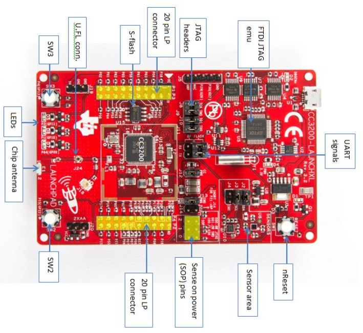
  • Monitoring and reporting, for this the CC3100 in conjunction with a MSP430F5529 will be used to post the data to a cloud based system such as Plot.ly to give real time information on the athletes sensor measurements.
Closing Summary
In closing I understand that this is a rather large project and will try my best to accomplish as much as possible. This is a project I am passionate about due to its ability to help athletes in the short term and potentially many more people in the long term. I believe that even if what I do does not directly get used it will have the potential to be used or inspire others to what other approaches are available in this interesting and exciting space.
Thankfully
Kas Lewis

Thursday, November 20, 2014

LPRS eRIC Development Kit - Review


p1010278.jpg

I would like to thank Element14 and LPRS for selecting me for this Road Test Review. This was an interesting and fun road test due to my past experience with the Texas Instruments CC3x00 SimpleLink family, LS Research ProFlex Zigbee and Anaren AIR Zigbee modules amongst others. I was very much looking forward at comparing the ease of use of the eRIC modules as well as the range such modules could give.


Unboxing
The packaging for these module was truly surprising. The box fits everything snuggly inside with almost no space to spare, this is a nice consideration as it allows for easy storage when the kit is no longer needed. The box is made from anti-static cardboard and anti-static foam. The kit contains two eRIC modules, two development boards, two antenna for the specified frequency (433/868/915 MHz),  two type A to Micro-B USB connectors, two 9V batteries and a Wireless Mike memory stick.

P1010206.JPGP1010208.JPG  p1010253.jpgp1010271.jpg
Figure 1. Opening the eRIC Development Kit and displaying the kits contents

The models are location specific, this means that a different frequency is used depending on the country the modules are sent to. Europe models use 434 MHz while North America modules use 868/915 MHz. The modules are easily set apart by the markings on the individual module. The Europe modules have a “4” in the lower right corner while those for North America have a “9”, this can be seen in the picture below.

p1010262.jpgp1010267.jpg
Figure 2. eRIC module with a distinct “9” announcing its North American designation


First Impressions
After opening the kit it is a simple step to get the kit working to see what the kit is capable of. It is this step that gives the user there first impressions of the kit and modules and aid in deciding where to move forward with such a unit or not.

The onboard demo allows for either choosing a predefined flashing sequence or an echo of the button press of a tester. The predefined sequence is useful in quickly and simply determining the range the modules can handle. To get this demo working it is a matter of 3 button presses on each development board respectively. This is a simple and easy process, button #1 is pressed and held for 2 seconds, LED #3 & #4 will flash twice and then either button #2 (transmitter) or #4 (receiver) is pressed to choose the functionality that module is to take.

p1010256.jpg
Figure 3. Test buttons located on the left side

Hardware overview
Modules
The eRIC modules are encased in a distinct gold plated RF shielding can with an opening for the u.fl connector and have 22 gold plated connection points. The connection points allow for the modules to be fully and easily used for a vast array of applications. The modules on the uC are also fully accessible allowing for high speed communication over SPI and I2C as well as lower speed communication over UART. There is also the ability to use the  GPIOs, ADCs and WDT all of this makes the eRIC an easy module to integrate into most projects. With 22 connection points at standard 0.1” pitch the module can easily be used with standard headers and breadboarded if needed. The different modules (North America vs. Europe) are easily distinguished from the number after the module’s eRIC marking.

p1010269.jpg
Figure 4. Development Kit with eRIC 9 module and Antenna (Battery not present)


Development Board
The modules fit easily and snugly into the development board and provides all necessary connections to the modules peripherals. The boards allow for a module to be soldered to the board or to use those pads as permanent test points. The development boards also provide a method to program the modules either through USB or through JTAG. There are 4 buttons to use for GPIO input and 4 LEDs for GPIO output allowing for crude debugging or program testing. Also included on the development board is an SMA connection for an external antenna. The antenna has been previously matched removing any need for set up by the end user. There is also a variable resistor for use with the modules accessible ADC. The on board battery connector allows for the development kit to work remotely and be a prototype substitute for a planned product.

The choice of battery is interesting due to its lower mAh (~500 mAh) compared to that of a AA battery (~1500 mAh). Considering the voltage regulators need to reduce the voltage from 9V to 3.3V instead of 4.5V to 3.3V the efficiency would definitely be lower. At the same time the use of a 9V battery allows for one battery to be used in a more compact form.  Since this is mainly for development this shorter run time would be acceptable.


easyRadio companion software
The kit comes with easy to use test software. The software includes easy configuration of all the basic modules wireless systems. These systems include UART baud rate, transmit power level, desired channel (frequency) as well as the over the air data rate. All of these settings allow for easy testing of the module in desired scenarios. This may include how the modules may interfere with or be disturbed by other systems, what is the optimal data rate so as not to lose data packets. Also included in the software is a test tab allowing for selecting high/low side and modulated carrier allowing for further testing of the RF signal with other systems. Also available in this tab is the ability to get the module version and the raw data being returned from the modules.

2014-11-18 01_04_21-Program Manager.jpg2014-11-18 01_06_09-Greenshot.jpg2014-11-18 01_05_39-Greenshot.jpg2014-11-18 01_06_26-Greenshot.jpg2014-11-18 01_06_41-Greenshot.jpg2014-11-18 01_07_16-Greenshot.jpg
Figure 5. The six screens viewable on the easyRadio Companion Software

The last tab allows for over the air transmission. This tab has an option for repeated sending at a rate of 1Hz as well a for a local echo. The one thing missing would be the ability to send large quantities of data in this test method so as to see what limits your unique situation encounter.

API
The modules come with what LPRS calls eROS (easyRadio operating system). This is a simple “operating system” to allow for a greater use of the modules subsystems. There is a large API (~100 functions) that allows for setting up the wireless, the UART, SPI, ADC, clock speed, interrupts etc. I have tested some of these calls and they seem to work with little issue, and it really helps to reduce the setup and prototyping stages.

The modules are coded using CCS from Texas Instruments and as this is not a foreign IDE there was little trouble using that as well. The code uses a predefined linker file as there is a bootloader on the modules that needs to be accommodated for. While this allows for security for LPRS’ code it makes coding slightly clumsy, its not a showstopper but it has some drawbacks. Over all the API it well defined, easy to follow and gives a lot of control of the module.


Range
Some basic testing was conducted with these units to see what type of range they have (a Spectrum analyzer would be awesome Element4… wink, wink). Since this is supposed to be a IoT module and presumably used for sensor networks there were two basic test done. The first was to place one unit  transmitting in one corner of a house while walking around with the second to determine when bits in the sequence where skipped. In a standard North American house both the the main floor as well as the basement where traversed with no missing bits in the sequence. The second test was a line of sight this was done by placing the unit first at shoulder height on a plastic stand and then on the ground transmitting. Again the second unit was receiving and was used to look for missing bits. The first test resulted in approximately 165 meters while the second test resulted in approximately 110 meters. While these numbers may seem small for the size and power consumption these are respectable numbers. Lastly both antennae were removed and as expected barely a meter out there was no longer any reception.

Comparison to CC3x00
As I have just completed a road test of the CC3x00 SimpleLink family it would be somewhat acceptable to compare at least the control of both products. For the most part the CC3x00s are a lot more complex and take longer to get up and running. Even with their added functionality they are more complex over all and harder to use than the eRIC modules. That being said both modules have their place in the IoT arena. For small sensor networks that could then relay information back to a single point the eRIC modules would be sufficient. However, for anything more complex I would suggest a CC3x00. Part of the reason for this is the lack of protocol on the eRIC modules. All communication is done via broadcast and therefore all addressing, message type would need to be implemented by the end user. While some will say this allows for flexibility it also can slow down some development.

Price point comparison vs features
For the price ($25) of these modules (not kits) they deliver a lot. They are easy to use, simple to set up and work out of the box. In comparison to the CC3100/CC3200 ($34/$23) they would be lacking a programer as at least one of them includes one and the other for an extra $15 it would be included. The eRIC kit on the other hand is $190 for a kit that only includes two modules any extra modules would need an antenna as well as a way to connect to the rest of your project, I’m not sure the extra $120 is worth it for the simplicity in the software.


Original post on Element14 can be found here

Wednesday, November 19, 2014

TI Wi-Fi CC3200 LaunchPad & CC3100 BoosterPack - Review


P1010237.JPGP1010227.JPG


I would like to thank Element14 for the opportunity to test these development kits and get the chance to see what they are capable of. These kits were a lot of fun to work with and were well suited to the project I was working on. Most of my work was focused on the CC3100 Boosterpack mounted on the MSP430F5529 as can be seen from my project. Towards the end I was working to migrate the code from the CC3100 to the CC3200 and generally did not find this to complicated. I will outline all of this as I go through my review.


Unboxing
The boxing for both the CC3100 and the CC3200 were similar and were in the standard Texas Instruments style. This has over the years made their boxes smaller and less elaborate, while some may find this unattractive it definitely helps when you are finished with a kit as it takes up less space in storage and ALL their boxes fit nicely on top of each other, THANK YOU Texas Instruments!

P1010232.JPGP1010221.JPG

Figure 2. Unboxing the CC3100 (left) and CC3200 (right)

Both kits came with a USB cable, the CC3100 uses the cable for optional alternative power and the CC3200 it to program and power the board. Both boards can be powered from alternative sources but incase these are not available the USB can be used. Jumpers on both boards are used to choose the power source being used and if by accident (or on purpose) the wrong setting is selected there is seemingly no harm done to the board.


Hardware Overview
The boards are the usual elegant red Texas Instruments PCBs. The boards are well labeled for ease of use and follow the BYOB specification allowing for ease of use with any Launchpad as well as integration with other Boosterpacks. The layout of the CC3100 and the CC3200 are similar except for the added programmer on the CC3200 PCB. Both units have a connection point for external power. The CC3200 has a connection point for 2xAA batteries to power the unit while removed from a PC or power mains, the CC3100 has a USB connector to power the unit for cases where it is used with a 20 pin Launchpad and is unable to get the power otherwise needed.

Figure 3. Layout of the CC3100 (left) and the CC3200 (right) modules

Both the CC3100 and the CC3200 have the ability to attach an external antenna via a hardware modification that includes moving a capacitor from one location to another. There is also the ability to test signal power and integrity from an inline U.FL connector. Unfortunately I did not have the correct antenna to test this functionality on these units but it would have been interesting to see if an external antenna would have helped the connectivity issues seen with this board. One nice touch to the CC3200 is the addition of onboard sensors, being a stand alone unit these added sensors allow for out of the box testing with the added ability to send real data over the network.


Software/API Overview
The software that accompanies the CC3x00 is well developed and documented. The CC3100 has examples for every use of the module allowing someone to quickly and easily get a project started. Since the CC3100 is predominantly paired with the MSP430F5529,there are examples for most if not all modules and functions included in this uC making getting a project started that much easier. For this reason alone the CC3100 + MSP430F5529 would be a very good place for anyone wanting to get further into Wi-Fi projects. As I only used the CC3200 in a limited capacity I can not fully coment of the number and usefulness of example code for the peripherals.

An interesting feature for the CC3100 is the ability to write code in Visual Studio and then use the CC31XXEMUBOOST to upload the code to the CC3100 and run the code. This allows those familiar with that environment as well as that form of programing to also easily access embedded Wi-Fi device programing. Again for this there are numerous examples to help someone get started on a project in such a manner.

The new demo code (version 1.0.0) removes all login information to a separate file making it easier to share and collaborate on projects without sharing your specific security information. On the topic of security, Texas Instruments has implemented an interesting mechanism to easily add embedded projects to your Wi-Fi network. SmartConfig uses either an Android or iOS app to send all the information (optionally) in an encrypted format, thereby removing the need to hardcode in the network the system will be used or or the need to wire in an external keyboard or some other entry device. Also, with regards to security, it should be noted that some of the ness capable uC such as the MSP430G2553 can not handle Wi-Fi security such as WAP, this is mainly due to memory limitations on the uC.

The only real downside to this module is with regards to the communication protocol. The SPI/UART commands to control the module are not published and therefore if you wanted to move from a Texas Instruments uC to an unsupported uC the hardware abstraction layer would need to be rewritten for this. That being said, Texas Instruments has gone one step further and has tried to outline how this change would be done. I have not attempted this or looked into it in great detail but I am assuming even with this it would not be as simple as simply sending the needed SPI commands for the few functions you may be interested in.


Getting started
I started of using the CC3100 as a replacement for the CC3000 and found this board from the start to be a lot simpler to use. While they both follow the both basic standards the CC3100 has a more logical and well thought out code style as well as a more complete firmware. To get this Boosterpack working I chose to use the MSP430F5529LP. The main reason for the MSP430F5529LP is the amazingly long list of examples provided. There appears to be a demo for each function of the CC3x00 which is very helpful in getting started and getting a huge boost on what ever project it is you may be working on. There is a caveat to this list though, there are a few demos that exceed the code limit for CCS and therefore can not be run on the MSP430F5529 (I have run onder versions, V0.52 I think, with no issue, so somehow from 0.52 to 1.0.0 something changed and it no longer works).

I did not try all the demos for a few reasons. There are approximately 30 code demos and they each have their own quirks to get them running. Some need just to input your WiFi information others may need a bit more, there are others that need a second module or even hardware  changes. Every demo is listed in the user guide with clear steps how to get them up and running.


Creating a Project
I signed up to for this Road Test to help work on a project I was interested in. The project was to read in data from a temperature and barometric pressure sensor and then in real time plot the data. The project used the TCP Demo and then modified the code one step at a time until the current state of the project was achieved. As the project functionality is outlined in the linked blog I will describe more of how the project evolved and the challenges faced getting to the state it is currently at as well as the useability of this boosterpack.

Having started with the CC3000 and finding that I could not send any packets due to some erroneous error flag I jumped at the chance to try the CC3100. Having looked over the CC3000 code for a while the CC3100 code was not too difficult to get into especially since it seemed to follow a similar yet more natural progression. The commands are well named and for the most part self explanatory. Adding functionality to a demo is relatively ease due to the well documented logically laid out code

I started by just trying to connect to the Wi-Fi access point, as I was in a basement I found this to be my first major hurdle with the CC3100. The laptop I was working on was registering low to slightly poor connection (~ -78dBm) but it was still functioning reasonably, the CC3100 on the other hand was having a very difficult time connecting. I tried various orientations and locations (moving even a few centimeters can have a large effect). I found this to be one negative difference from the CC3000, the CC300 had less of an issue connecting than the CC3100, while I am not sure if this is due to a change in antenna or some other hardware on the boards but it was noticeable in my case.

P1010235.JPG

Figure 4. Comparison of the CC3000 (left) with the CC3100 (right)

There was also an issue sending data to a remote server as the code would always return an error while sending the data. While Texas Instruments took the stance that there code was indeed correct, data was infact being received at the server side of the connection. For this testing Hercules was used and proved to be a very easy and reliable piece of test software. After stepping through the code it was clear to me that a conditional statement was not set correctly, changing this no longer produced an error but still allowed for code to be transmitted correctly. If there are some potential error cases that are no longer being caught I can not be 100% as I did not step through every case.

TCP socket application - Version 1.0.0
*******************************************************************************
Device is configured in default state
Device started as STATION
Connection established w/ AP and IP is acquired
Establishing connection with TCP server
Connection with TCP server established successfully
Error while sending the data
Started TCP serve

Figure 5. Message received from CC3100 displaying transmission error

While building up the project I also encountered hanging issues. When attempting to connect to the access point (AP) the software would somehow jump into an infinite loop that there was no way out of. After reinstalling the SDK a few times which would temporarily help the issue but only for so long. Trying to tell the debugger where to jump too, to hopefully break out of the loop, also resulted in going back to the same infinite loop. This issue was finally resolved by uploading new firmware to the board via the  CC31XXEMUBOOST. I believe the CC3100/CC3200 was released a bit too early as there were a lot of issues on the e2e forums that seemed related to issues you would not find in a more mature product.


Figure 6. CC3100 Mounted on CC31XXEMUBOOST

Summery
In summary the SimpleLink Wi-Fi family is a good and easy place to get into Wi-Fi. All the hardware and software are well labeled and documented. There are numerous examples on almost all uses of the code as well as hardware. The support for these boards is very good and is such that I have not seen on many other manufacturers forums. I would therefore highly recommend these units to anyone wanting to get started or move forward with Wi-Fi.

Related Issues


Original post on Element14 can be found here