The past week has been spent trying to get a reliable SPI connection between the MSP430F5529 and the Analog Devices sensors as well as mapping pin connections for all devices needed for this project.
SPI Connection
The initial design plan was to use one SPI module for all SPI devices, this would include the CC3100 as well as the accelerometers and temperature sensor. The spi.c file was altered to allow for multiple device selects and all code was changed through the tcp_socket demo project. Once this was cleaned up and compiling with no issues the code was tested with the CC3100 and found to be working reliably. The next step was to attach a second SPI device.
At this point interesting things started to happen. When the ADXL362 was connected as it should be (MISO <->MISO, MOSI<->MOSI…) the CC3100 no longer worked, however, switching the connections (MISO <->MOSI, MOSI<->MISO) the CC3100 proceeded to work again. Using a logic analyzer it was clear the SPI was communicating in both cases but possibly not correctly (clock ticks were missed due to sampling rates of the old Saleae Logic) . It was also pretty clear from the sample data that the SPI frequency was set to 12 MHz. Once this was discovered and realizing it was not a hardware issue (verified using a Bus Pirate to talk to the ADXL362) the datasheet for the ADXL revealed the clock speed for the device MUST be between 1 MHz and 5 MHz (or 8 MHz depending on datasheet version). The Plan now is to write a new SPI driver for the ADI devices that will run at an acceptable clock rate for ALL the needed devices (ADXL362 1MHz - 5MHz, ADXL375 < 5 MHz, ADT3720 - Unknown). Once reliable communication has been established correct interpretation of input data will be worked out to enable proper interpretation and use of sensor data.
UART Code Removal
Also this week, time was spent removing code to control the CC3100 via UART. This was done to increase code readability and to remove possible confusion within the code. This was also done to help identify unused pins that may be used for the UART control of the CC3100. During this process the overall understanding of the code was greatly increased.
Pin Mapping
Since there was no clear indication of what pins were free, a quick code review was done to find all used pins and what they were used for. This was done to find all available pins and to correctly detail the used pins. As can be seen in the table below the CC3100 has a lot of pins broken out but only six are used. There are four for SPI, one for interrupts and one to enable and disable the CC3100, this excludes the 3.3 V rail and ground.
Once these were eliminated from the list six analog pins were selected, these would be set aside for the ADXL377 and time permitting the heart rate monitor. These were chosen next as there are only a limited number of analog pins on the MSP430F5529 and it was preferable to try have them consecutively numbered to potentially allow for easier programing.
Once the analog pins were selected the SPI for the ADI devices and their chip selects were chosen. All pins assigned so far can be seen in the table below.
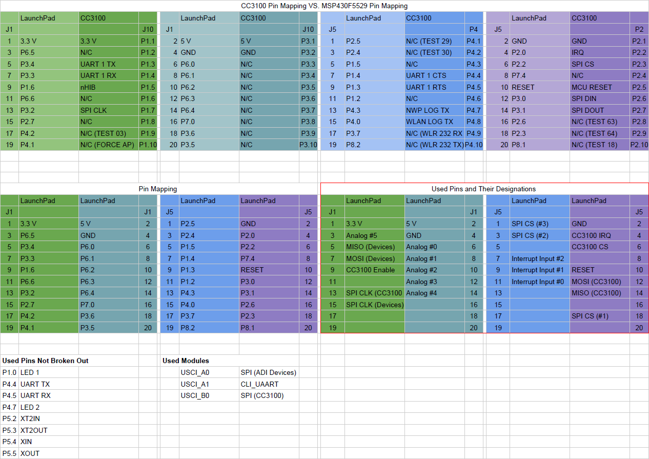
Table 1. Pin Mapping For MSP430F5529 & CC3100
Next Steps
This coming week will be spent getting all SPI devices working correctly and reporting back some data (Device ID) and formatting that data correctly. Once the SPI modules are working correctly and their data is correctly interpreted the ADC module will be attempted.
It may be obvious by now, but the user interface has been neglected at this point due to complexity in the learning curve for QT. For now data will either be sent to plot.ly for plotting at a decimated rate or logged on a local computer in a not athsetic interfcae, something like a terminal.
No comments:
Post a Comment