Introduction
I would like to thank Element14 and Texas Instruments for selecting me for this roadtest. I applied to review the TI Motor Drive Bundle because of a previous experience with the BOOSTXL-DRV8301 boosterpack and a not so compatible launchpad. I have previously reviewed this boosterpack with less than favourable results. I was therefore hoping that after 3 years of availability, the documentation and support would have improved.
Unboxing & First impressions
Element14 has worked with TI to deliver these boards as complete evaluation kit. The packaging has therefore been altered to reflect this. The three components, each individually packaged, come shipped in a single kit box. The launchpad is packaged in the standard TI box. The DRV8301 on the other hand is shipped in what has been labeled a new product box. If this was a new product, as it may have been during my initial review, this would be acceptable. Its now substanily later in the products life and this generic, oversized box reflects an apathy or disinterest towards this product. The provided motor (DN4240S24-026-TI) is shipped wrapped in bubble wrap. As a perk, a pen with a screwdriver in the back and a level and ruler on the side has been included.
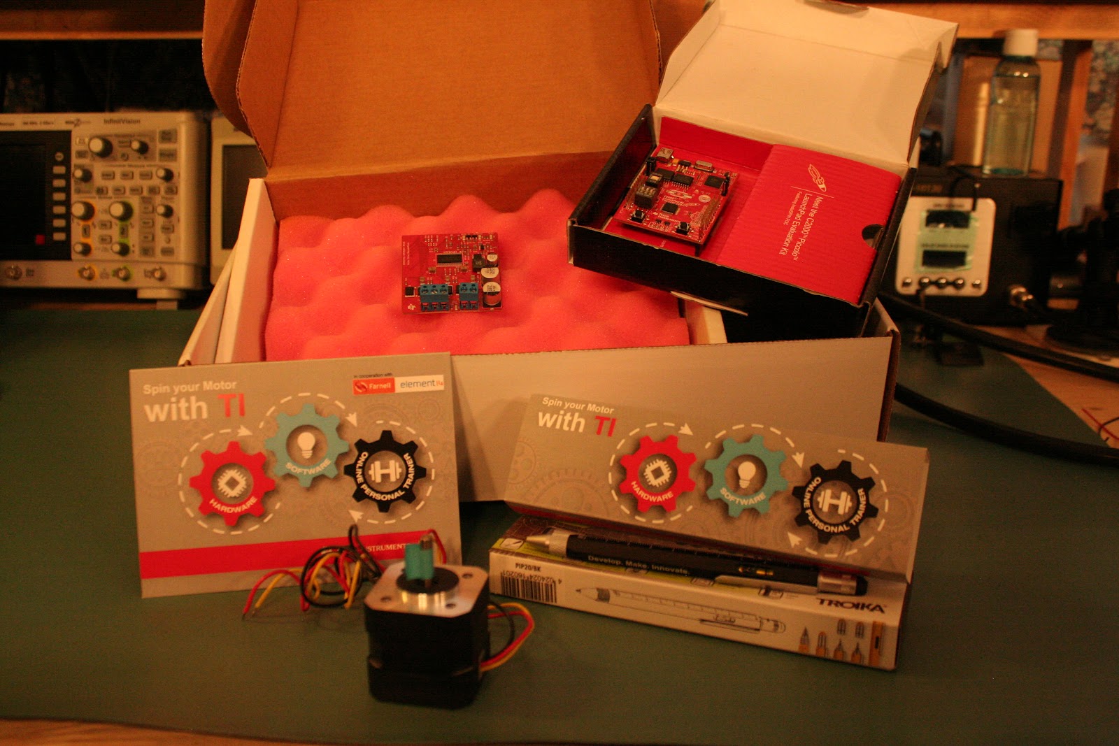
Kit contents as assembled by TI in partnership with Furnell/Newark
The getting started guide for the LAUNCHXL-F28027 has a simple demo to let you know the board is working. The demo interestingly contains two parts. The first demo is done with no PC connected. Once powered up a reference temperature is take. If the temperature changes, the change is reflected on the LEDs to indicate the difference. A new reference value can be set by pressing the S3 switch.
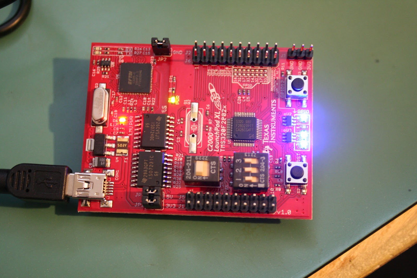
Demo: LEDs displaying change in temperature from initial setpoint
An extension of the first demo is accessed by connecting the LAUNCHXL-F28027 to a PC. After connecting the board, configuring the terminal (115200, 8, No parity, 1 stop) and pressing reset, the board display a text version of the TI symbol.
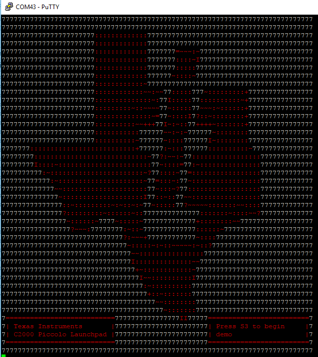
Terminal after resetting the F28027F
The display prompts you to press the S3 button. This again begins the temperature demo. Instead of only having the LEDs to inform you of the change, the measured value is updated at the bottom of the display.
The DRV8301 doesn't have a quickstart program to run even though there is a quick start guide. Any demo software for this boosterpack is found in the motorware software package and will be look at later in the review.
Getting Started
The various getting started guides all demonstrate how to configure the onboard switches and jumpers before starting. Once these are set there is little help to get you any further.
Proceeding to look through Motorware which had previously installed didn’t help. Knowing that this is an InstaSPIN-FOC board I looked under this section first. Unfortunately there are only projects listed there with no documentation. Attempting to use the Universal GUI to get started revealed the documentation for this software was lacking.
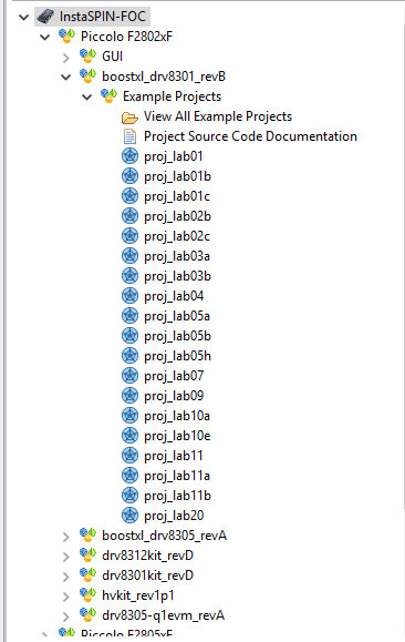
MotorWare labs available for the 8301 Rev B,, notice no documentation listed
Fortunately I was directed by a fellow member of Element14 (najath) to look in the Motorware software for further information. More specifically najath specified to look under the resources section (Resources > Launchpads > F28027F Launchpad). The “Kit Readme First” provides some information but nothing that has not already been provided from the various other getting started guides. The “GUI Quick Start Guide” is also the same as listed under InstaSPIN-FOC. Thankfully najath provided some further instructions. Under “Training:User’s Guides, Labs, Tutorials” is a PDF called “InstaSPIN Projects and Labs User's Guide”. This guide finally gets a user moving forward with this kit.
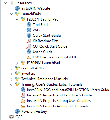
The resources section has a bit more information but, nothing particularly useful under the F28027F section
After spending a considerable amount of time to get to the kit working it became abundantly clear that TI had not made much, if any progress with this kit since my last review. The main difference between the current and previous review is the help provided from the Element14 community, something I don’t believe I got from TI’s e2e forum on previous attempts.
Documentation
The documentation for this kit has already been mentioned in passing. There is however a decent amount more to be said about this. The quick start guides, of which there seem to be an abundance, don’t point a user in any meaningful direction. The getting started guide for the launchpad shows the user how to configure the board and run the preprogrammed demos. It then points a user to CCS or ControlSUITE for anything further the user may want to do. This may be pretty standard for a getting started guide but, in this case the instructions don't lead to anything concrete to help a user move forward.
Sadly the getting started guide for the DRV8301 is worse then this. After explaining how to setup the hardware, and not really explaining how to connect the motor we arrive at step VI. If anything has been intuitive or well explained until now TI has made sure to rectify that. This last step simply states “Enable your control algorithm and spin that motor”. If this is unclear then TI suggest using MotorWare to get started.

Step 4 listed in the 8301 getting started guide, “Enable your control algorithm and spin that motor”
As has already been outline in the getting started section, this is more complicated than it would appear. There is no clear starting point once MotorWare is opened up. It should be mentioned at the END of the instructions for each project in MotorWare there is one line “Follow the InstaSPIN Projects and User’s Guide to Get Started”.

Atr the END of each project TI lists where to find more information about getting the lab working
This concept of doing things out of order and in a non intuitive manor seems to be common with this kit. The Quick Start Guide for the Universal GUI also lists all the steps needed to run the software including clicking on run. Only after completing the lab, TI explains how to setup the hardware that the software runs on. Just before setting up the hardware but, after the completion of the lab, is the explanation of the GUI’s interface.
Other issues include incorrect referencing/labeling of tables in the lab guide. Steps that are not relevant to some launchpads, including the one included with this kit, are not commented as such. Missing steps, such as those needed to get the Universal GUI working. The steps for the GUI were eventually stumbled upon by reading the readme file in the InstaSPIN_F2802xFUNIVERSAL folder. The GUI has also been changed since the guide for it was last updated in 2015. There have been some components added and others removed. This leaves a user unclear what the functionality of these components are.
Overall TI has really dropped the ball with regards to its documentation for this product. The time between this product first being introduced and now has not been used to streamline the process to get a new user from demo to product. Nore has it been used to increase ease of use. I would be beneficial for TI and it’s customers if these documents where revamped. It would also be helpful if there was one getting started guide with a logical progression to get this kit running with minimum hiccups along the way.
Software
Once the documentation has been worked out and, the single useful starting point found, there is a lot of software to work through. Because of the complexities of the Piccolo along with the those of controlling a motor TI has provided a HAL layer. This allows a user to focus on getting the system working as needed and not worry about setting up registers. Another reason not made clear at first, is the need to hide the code running in the FOC. As this is proprietary and TI not wanting it shared, this HAL also provides access without giving away anything. In order to help the user understand each of the functions are 20+ labs each with multiple parts. While some of these labs are not relevant to the LAUNCHXL-F28027 there are still a large number of demos helping someone working with this kit to understand how to get their project working.
Each lab is provided with complete code that compiles out of the box. Sadly not all the code is well explained and there is a decent amount of following functions to get to the root of their intent. This added effort adds time and complexity to getting through each lab. Along with a unclear explanation of the software in each lab is an equally brief explanation in the lab manual. It is definitely possible to work out the ambiguities but this again adds time. One major issue in this regard is the lack of mentioning when a specific part of the software is not relevant to a microcontroller. Some of the labs require code changes to be made in order to get a better understanding of what the software is doing. The sections in the lab manual are not labeled as not being relevant to different controllers. The only way to infer this is by looking at the #ifdef statements at the top of each section of code.
Another issue with the software and its associated documentation is the assumption of specific knowledge. There are terms and abbreviations used that are not explained or done so very briefly. This would be acceptable if there was some reference information provided to help a new user to learn more, but there are no footnotes or references.
Regarding this specific kit, each project uses a header file to pull in parameters that the user can set for their motor. TI has kindly provided parameters for 16 different motors. This allows for a user to easily switch over to a different motor without needing to figure out the parameters of that motor. TI however forgot or decided to not include the parameters for the motor (DN4240S24-026-TI) that is shipped with this kit. Adding to this issue is the lack of availability of any documentation for this motor. Only after contacting the manufacturer of the motor was I able to get the documentation for it. This one page document still did not provide all the needed information. There is however a page, that was pointed out by another element14 member (MARK2011), that doesn't seem to be anyway linked to the kit or the product identifier that does have the full specs.

DN4240S24-026-TI datasheet as received from the manufacturer
Hardware
The hardware provided in this kit has a few interesting factors. The first and most obvious is the ill fitting nature between the LAUNCHXL-F28027F and the BOOSTXL-DRV8301. The switch S4’s form factor prevents the boosterpack from seating properly on the launchpad.
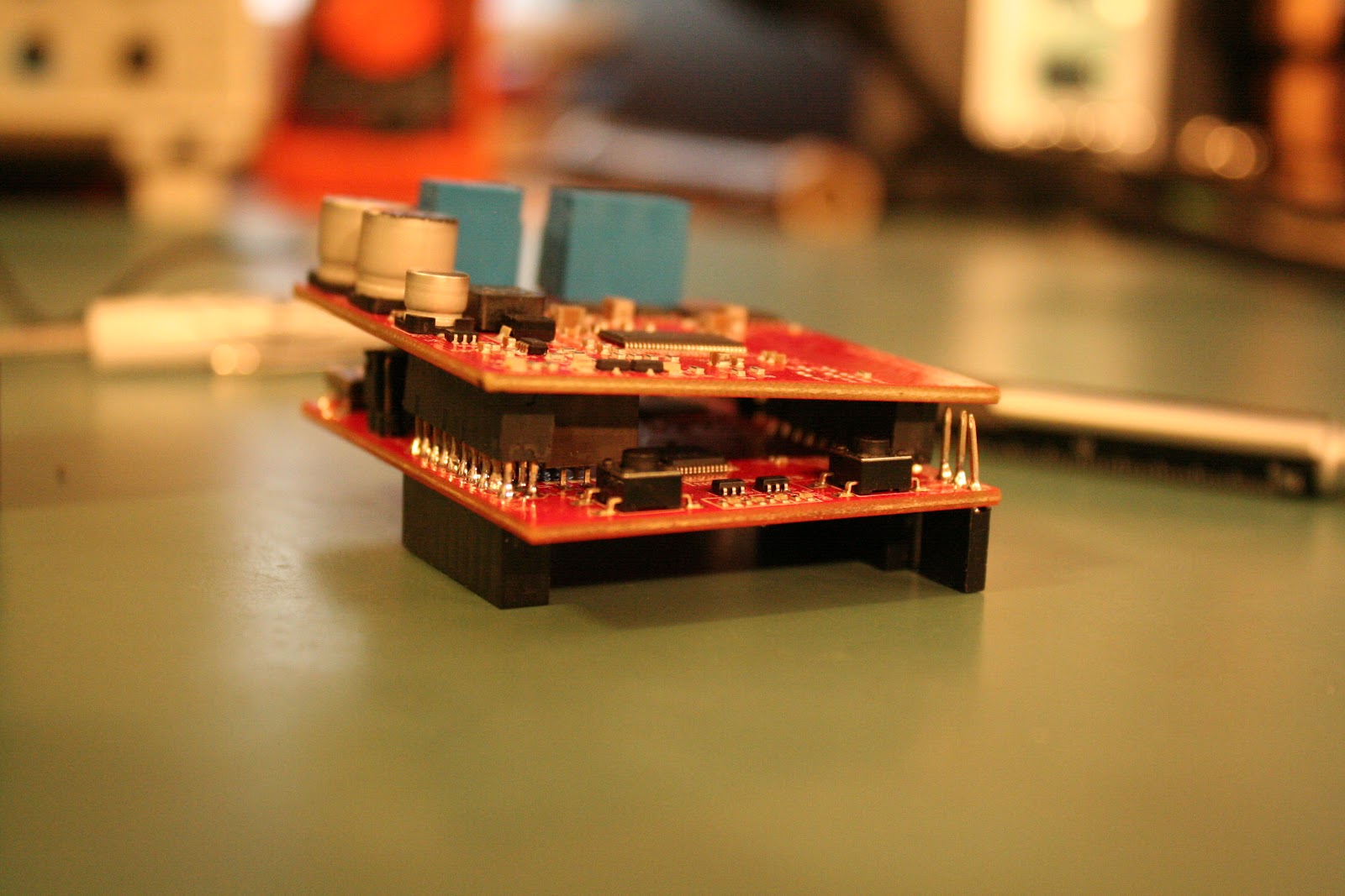
The S3 switch on the F28027 launchpad can interfere with the DRV8301s ability to be correctly seated
A workaround for this is to provide an extra set of headers to increase the clearance between the bottom of the boosterpack and the switch. The placement of this switch as well as S1 means that any change to these switches requires that the boosterpacks be removed. This again is solved by adding the extension

Headers added to the F28027 launchpad allow the DRV8301 to clear the S3 switch
Another interesting issue noticed is the seemingly incompatibility between the F28027F and the F28027. The previous review I did was supposed to contain an F28027F but instead I received a F28027. Since TI specifies these are pin compatible and the schematics for the LAUNCHXL-F28027/F don’t mention any alterations depending on the provided chips the F28027 was swapped for a F28027F. Unfortunately this did not resolve any issues and the board does not perform like one containing a F28027F.
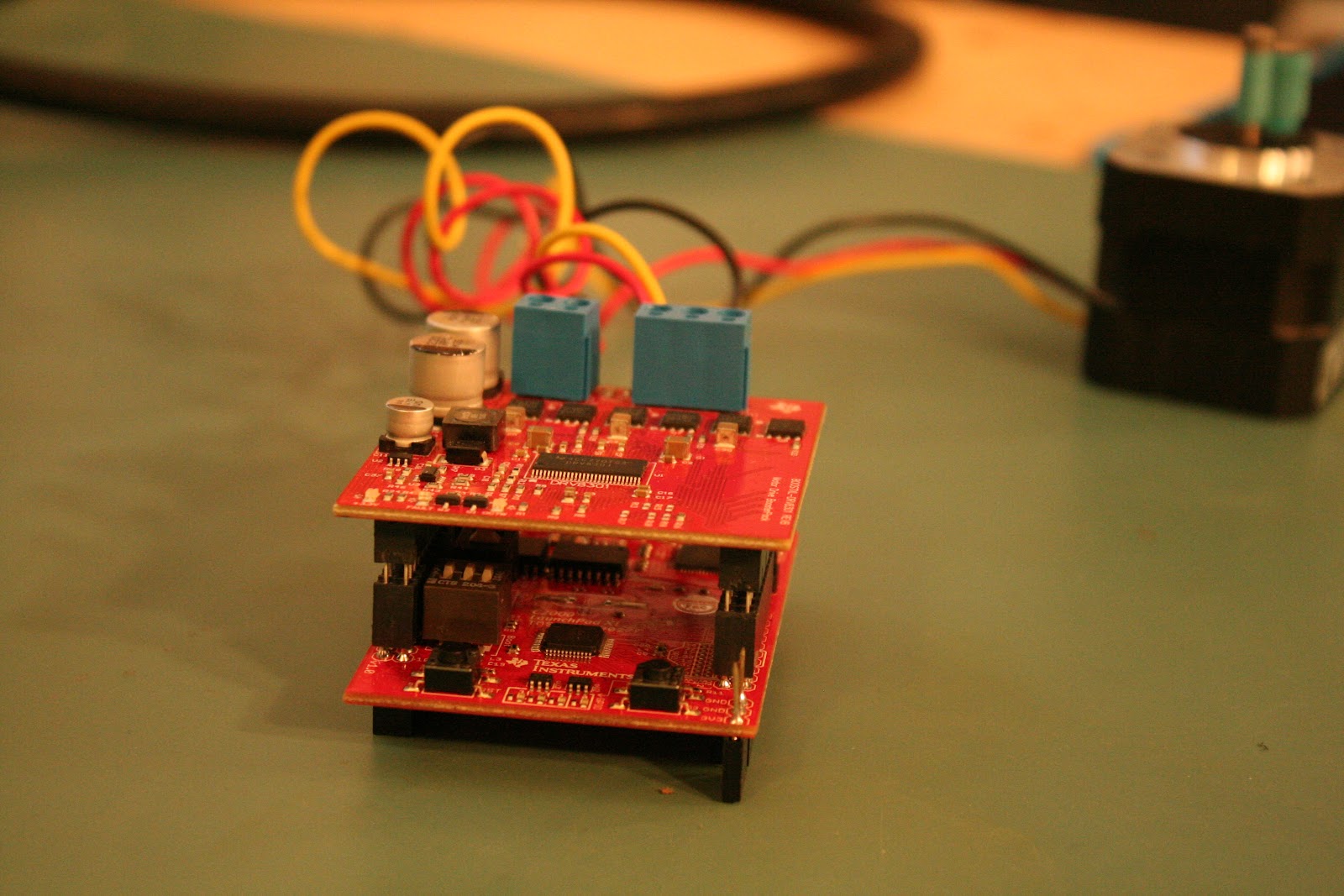
On the positive side, TI has positioned the BOOSTXL-DRV8301 on top of the LAUNCHXL-F28027F in such a way as to keep S2 and S3 (the two user push buttons) accessible during operation. This allows for those buttons be incorporated into a design without concern for accessibility.
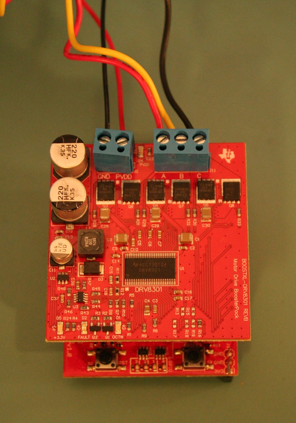
The two user switches have been well placed allowing them to be accessed even when a boosterpack is mounted
SUPPORT
TI included with this kit 6 hours of free online help with your own “personal trainer”. This is probably the one thing TI has done well to move this product forward. The kit includes a card with a TI employees name and email address. Contacting the employee reveals he is someone well acquainted with the software for this kit. I was also informed that should more than the advertised 6 hours be needed that would not be an issue. The help includes anything from just answering a few short questions to getting a walk through on the software. The idea is that after the personal help you should be well on your way with your project. In the few interactions I had through this service I found the employee to be both helpful and courteous.
TI’s e2e forum is still available for this product so if immediate help is needed (the personal trainer is located in Germany) you can try find answers there. The one big difference between the personal trainer and e2e is accountability. By directing your question to one person instead of to a broad forum is there is one person responsible. This leads to both better and more timely responses.
Moving forward
Having spent a decent amount of time getting to know this kit I am looking forward to using it further both as a learning tool as well as in future projects. Something that I have found this kit to be useful for other than motor control is it sability to teach control theory. Because there are so many variables in controlling a motor and both the LAUNCHXL-F28027F and the BOOSTXL-DRV8301 allow for these variables to be controlled this is a great platform for learning applying these control strategies.
I would also like to complete all the labs associated with this kit. As previously mentioned working through each lab and following each function call down to its base call to get a better understanding takes time. I have therefore been unable to complete all 19 labs for the BOOSTXL-DRV8301. Once this has been completed I would like to try implement this kit in a boat project I have been looking at. This would be used control the propulsion propeller allowing for such things as cavitation mitigation to be implemented
Conclusion
Overall this is a quilty kit provided from TI in partnership with Element14. The software and HAL layers are well implemented. There are sufficient demonstrations to allow a user to learn how to use the kit for any application they may have in mind.
Sadly these great qualities are overshadowed by the badly written getting started guide and the abundance of them. Had TI selected to have one getting started guide for the BOOSTXL-DRV8301 that clearly outlined the steps to get the kit working with the demo software this kit would be a lot more useful. Along with this had TI put more effort into the lab manual to explain what the various functions are doing as well as what functions work with what kit that would have helped as well.
I am therefore looking forward to working more with this kit to learn about motor control as well as control theory in general. I am also hoping to implement more motors into my projects now that I have become acquainted with this product and its use cases. For others wanting to learn about motor control and have the time and energy to go through the many pages of documentation and lengthy lines of code, this kit is definitely useful and has a lot to offer.