Showing posts with label LaunchPad. Show all posts

Monday, February 12, 2018

TI Motor Drive Bundle (LAUNCHXL-F28027, BOOSTXL-DRV8301) & MotorWare - How Easy is it to Get Your Motor Spinning

Introduction

I would like to thank Element14 and Texas Instruments for selecting me for this roadtest. I applied to review the TI Motor Drive Bundle because of a previous experience with the BOOSTXL-DRV8301 boosterpack and a not so compatible launchpad. I have previously reviewed this boosterpack with less than favourable results. I was therefore hoping that after 3 years of availability, the documentation and support would have improved.

Unboxing & First impressions

Element14 has worked with TI to deliver these boards as complete evaluation kit. The packaging has therefore been altered to reflect this. The three components, each individually packaged, come shipped in a single kit box. The launchpad is packaged in the standard TI box. The DRV8301 on the other hand is shipped in what has been labeled a new product box. If this was a new product, as it may have been during my initial review, this would be acceptable. Its now substanily later in the products life and this generic, oversized box reflects an apathy or disinterest towards this product. The provided motor (DN4240S24-026-TI) is shipped wrapped in bubble wrap. As a perk, a pen with a screwdriver in the back and a level and ruler on the side has been included.
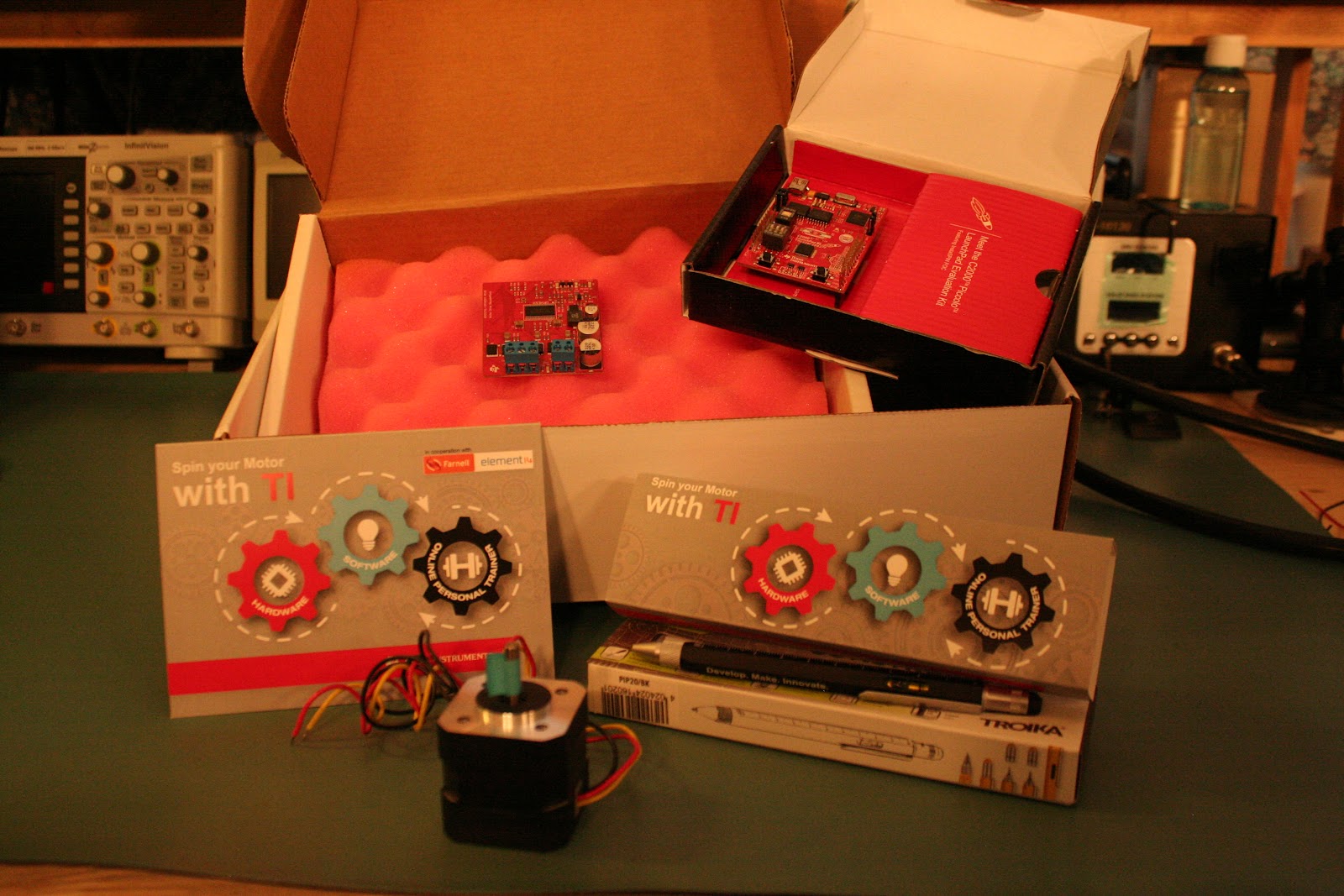
Kit contents as assembled by TI in partnership with Furnell/Newark

The getting started guide for the LAUNCHXL-F28027 has a simple demo to let you know the board is working. The demo interestingly contains two parts. The first demo is done with no PC connected. Once powered up a reference temperature is take. If the temperature changes, the change is reflected on the LEDs to indicate the difference. A new reference value can be set by pressing the S3 switch.
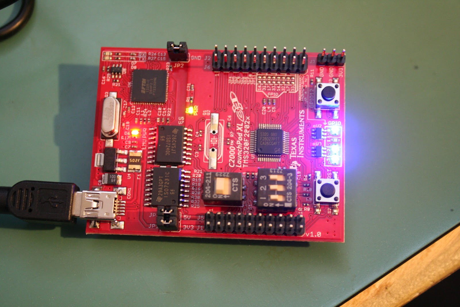
Demo: LEDs displaying change in temperature from initial setpoint

An extension of the first demo is accessed by connecting the LAUNCHXL-F28027 to a PC. After connecting the board, configuring the terminal (115200, 8, No parity, 1 stop) and pressing reset, the board display a text version of the TI symbol.
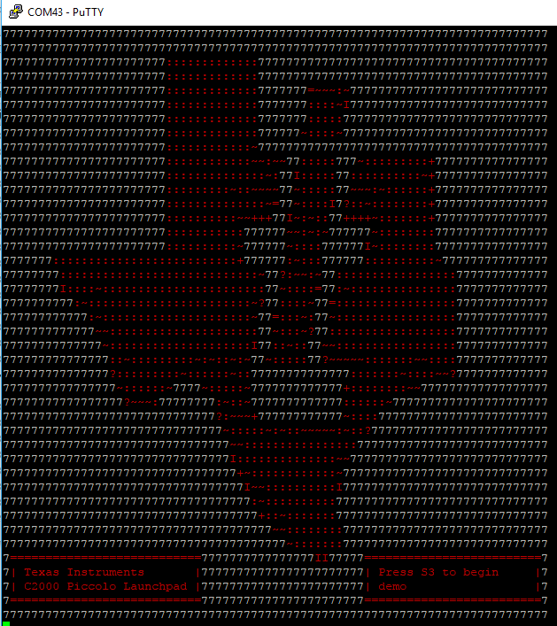
Terminal after resetting the F28027F

The display prompts you to press the S3 button. This again begins the temperature demo. Instead of only having the LEDs to inform you of the change, the measured value is updated at the bottom of the display.

The DRV8301 doesn't have a quickstart program to run even though there is a quick start guide. Any demo software for this boosterpack is found in the motorware software package and will be look at later in the review.

Getting Started

The various getting started guides all demonstrate how to configure the onboard switches and jumpers before starting. Once these are set there is little help to get you any further.
Proceeding to look through Motorware which had previously installed didn’t help. Knowing that this is an InstaSPIN-FOC board I looked under this section first. Unfortunately there are only projects listed there with no documentation. Attempting to use the Universal GUI to get started revealed the documentation for this software was lacking.
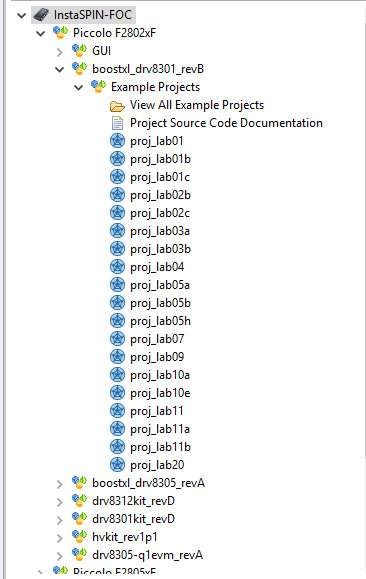
MotorWare labs available for the 8301 Rev B,, notice no documentation listed

Fortunately I was directed by a fellow member of Element14 (najath) to look in the Motorware software for further information. More specifically najath specified to look under the resources section (Resources > Launchpads > F28027F Launchpad). The “Kit Readme First” provides some information but nothing that has not already been provided from the various other getting started guides. The “GUI Quick Start Guide” is also the same as listed under InstaSPIN-FOC. Thankfully najath provided some further instructions. Under “Training:User’s Guides, Labs, Tutorials” is a PDF called “InstaSPIN Projects and Labs User's Guide”. This guide finally gets a user moving forward with this kit.
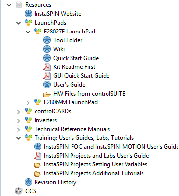
The resources section has a bit more information but, nothing particularly useful under the F28027F section

After spending a considerable amount of time to get to the kit working it became abundantly clear that TI had not made much, if any progress with this kit since my last review. The main difference between the current and previous review is the help provided from the Element14 community, something I don’t believe I got from TI’s e2e forum on previous attempts.

Documentation

The documentation for this kit has already been mentioned in passing. There is however a decent amount more to be said about this. The quick start guides, of which there seem to be an abundance, don’t point a user in any meaningful direction. The getting started guide for the launchpad shows the user how to configure the board and run the preprogrammed demos. It then points a user to CCS or ControlSUITE for anything further the user may want to do. This may be pretty standard for a getting started guide but, in this case the instructions don't lead to anything concrete to help a user move forward.

Sadly the getting started guide for the DRV8301 is worse then this. After explaining how to setup the hardware, and not really explaining how to connect the motor we arrive at step VI. If anything has been intuitive or well explained until now TI has made sure to rectify that. This last step simply states “Enable your control algorithm and spin that motor”. If this is unclear then TI suggest using MotorWare to get started.

Step 4 listed in the 8301 getting started guide, “Enable your control algorithm and spin that motor”

As has already been outline in the getting started section, this is more complicated than it would appear. There is no clear starting point once MotorWare is opened up. It should be mentioned at the END of the instructions for each project in MotorWare there is one line “Follow the InstaSPIN Projects and User’s Guide to Get Started”.

Atr the END of each project TI lists where to find more information about getting the lab working

This concept of doing things out of order and in a non intuitive manor seems to be common with this kit. The Quick Start Guide for the Universal GUI also lists all the steps needed to run the software including clicking on run. Only after completing the lab, TI explains how to setup the hardware that the software runs on. Just before setting up the hardware but, after the completion of the lab, is the explanation of the GUI’s interface.

Other issues include incorrect referencing/labeling of tables in the lab guide. Steps that are not relevant to some launchpads, including the one included with this kit, are not commented as such. Missing steps, such as those needed to get the Universal GUI working. The steps for the GUI were eventually stumbled upon by reading the readme file in the InstaSPIN_F2802xFUNIVERSAL folder. The GUI has also been changed since the guide for it was last updated in 2015. There have been some components added and others removed. This leaves a user unclear what the functionality of these components are.

Overall TI has really dropped the ball with regards to its documentation for this product. The time between this product first being introduced and now has not been used to streamline the process to get a new user from demo to product. Nore has it been used to increase ease of use. I would be beneficial for TI and it’s customers if these documents where revamped. It would also be helpful if there was one getting started guide with a logical progression to get this kit running with minimum hiccups along the way.

Software

Once the documentation has been worked out and, the single useful starting point found, there is a lot of software to work through. Because of the complexities of the Piccolo along with the those of controlling a motor TI has provided a HAL layer. This allows a user to focus on getting the system working as needed and not worry about setting up registers. Another reason not made clear at first, is the need to hide the code running in the FOC. As this is proprietary and TI not wanting it shared, this HAL also provides access without giving away anything. In order to help the user understand each of the functions are 20+ labs each with multiple parts. While some of these labs are not relevant to the LAUNCHXL-F28027 there are still a large number of demos helping someone working with this kit to understand how to get their project working.

Each lab is provided with complete code that compiles out of the box. Sadly not all the code is well explained and there is a decent amount of following functions to get to the root of their intent. This added effort adds time and complexity to getting through each lab. Along with a unclear explanation of the software in each lab is an equally brief explanation in the lab manual. It is definitely possible to work out the ambiguities but this again adds time. One major issue in this regard is the lack of mentioning when a specific part of the software is not relevant to a microcontroller. Some of the labs require code changes to be made in order to get a better understanding of what the software is doing. The sections in the lab manual are not labeled as not being relevant to different controllers. The only way to infer this is by looking at the #ifdef statements at the top of each section of code.

Another issue with the software and its associated documentation is the assumption of specific knowledge. There are terms and abbreviations used that are not explained or done so very briefly. This would be acceptable if there was some reference information provided to help a new user to learn more, but there are no footnotes or references.

Regarding this specific kit, each project uses a header file to pull in parameters that the user can set for their motor. TI has kindly provided parameters for 16 different motors. This allows for a user to easily switch over to a different motor without needing to figure out the parameters of that motor. TI however forgot or decided to not include the parameters for the motor (DN4240S24-026-TI) that is shipped with this kit. Adding to this issue is the lack of availability of any documentation for this motor. Only after contacting the manufacturer of the motor was I able to get the documentation for it. This one page document still did not provide all the needed information. There is however a page, that was pointed out by another element14 member (MARK2011), that doesn't seem to be anyway linked to the kit or the product identifier that does have the full specs.

DN4240S24-026-TI datasheet as received from the manufacturer

Hardware

The hardware provided in this kit has a few interesting factors. The first and most obvious is the ill fitting nature between the LAUNCHXL-F28027F and the BOOSTXL-DRV8301. The switch S4’s form factor prevents the boosterpack from seating properly on the launchpad.
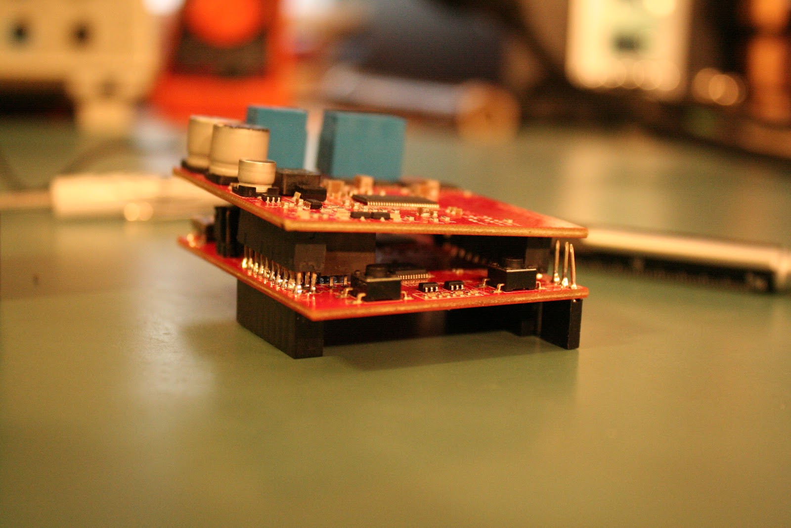
The S3 switch on the F28027 launchpad can interfere with the DRV8301s ability to be correctly seated

A workaround for this is to provide an extra set of headers to increase the clearance between the bottom of the boosterpack and the switch. The placement of this switch as well as S1 means that any change to these switches requires that the boosterpacks be removed. This again is solved by adding the extension

Headers added to the F28027 launchpad allow the DRV8301 to clear the S3 switch

Another interesting issue noticed is the seemingly incompatibility between the F28027F and the F28027. The previous review I did was supposed to contain an F28027F but instead I received a F28027. Since TI specifies these are pin compatible and the schematics for the LAUNCHXL-F28027/F don’t mention any alterations depending on the provided chips the F28027 was swapped for a F28027F. Unfortunately this did not resolve any issues and the board does not perform like one containing a F28027F.

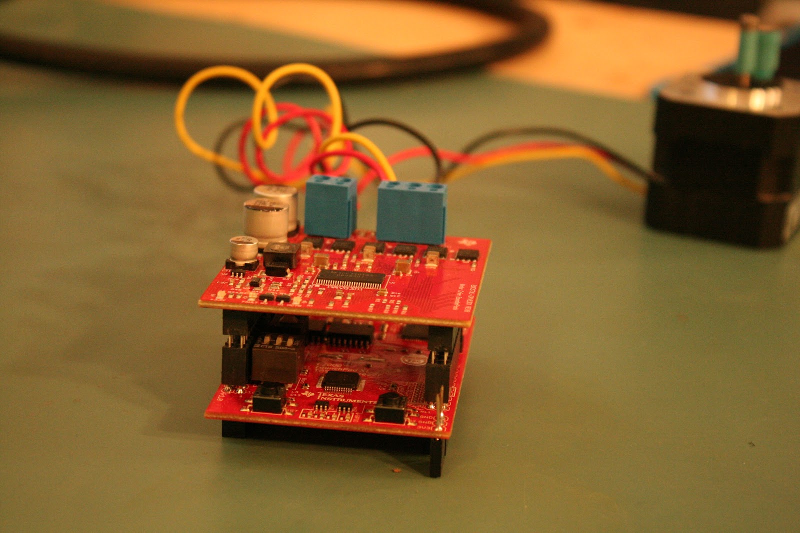
On the positive side, TI has positioned the BOOSTXL-DRV8301 on top of the LAUNCHXL-F28027F in such a way as to keep S2 and S3 (the two user push buttons) accessible during operation. This allows for those buttons be incorporated into a design without concern for accessibility.
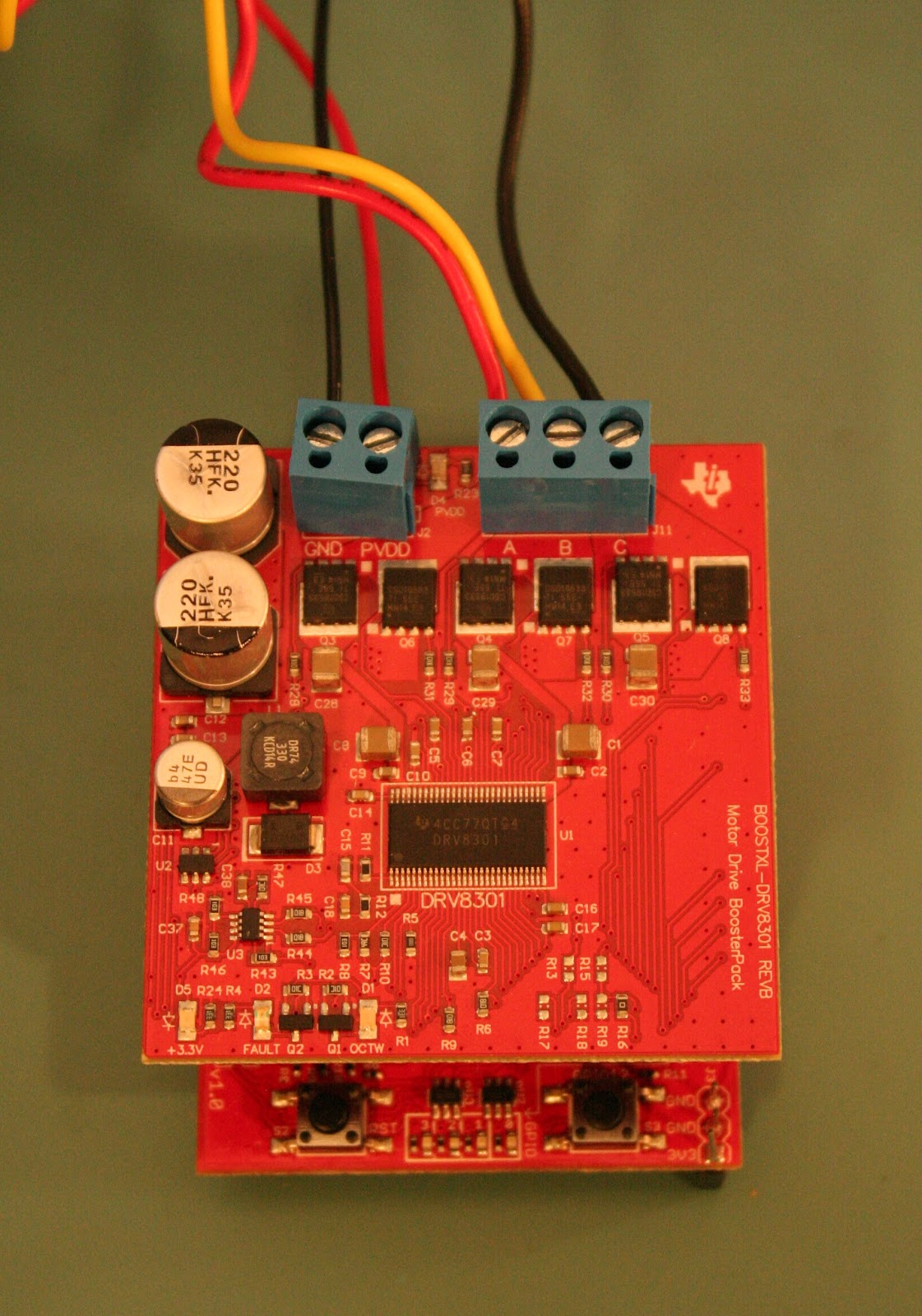
The two user switches have been well placed allowing them to be accessed even when a boosterpack is mounted

SUPPORT

TI included with this kit 6 hours of free online help with your own “personal trainer”. This is probably the one thing TI has done well to move this product forward. The kit includes a card with a TI employees name and email address. Contacting the employee reveals he is someone well acquainted with the software for this kit. I was also informed that should more than the advertised 6 hours be needed that would not be an issue. The help includes anything from just answering a few short questions to getting a walk through on the software. The idea is that after the personal help you should be well on your way with your project. In the few interactions I had through this service I found the employee to be both helpful and courteous.

TI’s e2e forum is still available for this product so if immediate help is needed (the personal trainer is located in Germany) you can try find answers there. The one big difference between the personal trainer and e2e is accountability. By directing your question to one person instead of to a broad forum is there is one person responsible. This leads to both better and more timely responses.

Moving forward

Having spent a decent amount of time getting to know this kit I am looking forward to using it further both as a learning tool as well as in future projects. Something that I have found this kit to be useful for other than motor control is it sability to teach control theory. Because there are so many variables in controlling a motor and both the LAUNCHXL-F28027F and the BOOSTXL-DRV8301 allow for these variables to be controlled this is a great platform for learning applying these control strategies.

I would also like to complete all the labs associated with this kit. As previously mentioned working through each lab and following each function call down to its base call to get a better understanding takes time. I have therefore been unable to complete all 19 labs for the BOOSTXL-DRV8301. Once this has been completed I would like to try implement this kit in a boat project I have been looking at. This would be used control the propulsion propeller allowing for such things as cavitation mitigation to be implemented

Conclusion

Overall this is a quilty kit provided from TI in partnership with Element14. The software and HAL layers are well implemented. There are sufficient demonstrations to allow a user to learn how to use the kit for any application they may have in mind.

Sadly these great qualities are overshadowed by the badly written getting started guide and the abundance of them. Had TI selected to have one getting started guide for the BOOSTXL-DRV8301 that clearly outlined the steps to get the kit working with the demo software this kit would be a lot more useful. Along with this had TI put more effort into the lab manual to explain what the various functions are doing as well as what functions work with what kit that would have helped as well.

I am therefore looking forward to working more with this kit to learn about motor control as well as control theory in general. I am also hoping to implement more motors into my projects now that I have become acquainted with this product and its use cases. For others wanting to learn about motor control and have the time and energy to go through the many pages of documentation and lengthy lines of code, this kit is definitely useful and has a lot to offer.
Original post on Element14 can be found here

Friday, September 30, 2016

MSP430F5529 Power Logger with AT&T M2X

MSP430F5529-M2X-MCP39F511.png
In the previous blog the issue of having too many options when choosing an IoT solution was introduced. As a way to judge how easy it it is to select a solution, a project was proposed that could be implemented using different hardware and software. Once these projects are implemented on these platforms a comparison will be done to determine, from a prototyping perspective, what is an easy platform to use.


Usage Case

Power consumption at home and in the office is becoming a more conscious issue. The concept of leaving appliances to use whatever power they need at all hours of the day and night is no longer socially acceptable. Unfortunately most people do not know what power they are consuming or when they consume it. For these reasons this project aims to monitor power consumption of a device in either a residential or commercial setting.


Hardware & Setup

The hardware used to prototype this project consists of three components. The code that controls the various components is run on the MSP430F5529. The power consumption data is acquired using a MCP39F511 power monitoring IC from Microchip. Lastly the data is uploaded to the cloud via a CC3100 SimpleLink WiFi boosterpack that provides WiFi connectivity.


This initial implementation of the project was decided to be implemented on an MSP430 launchpad and programmed using Energia. The simplicity of both the hardware and software was also a factor in this selection. Another factor was the ability to easily move the prototype to a production model. The MSP430FR5969 was initially selected for this project because of the desire for a platform with a minimal number prebuilt examples. Unfortunately due to connectivity issues that were not immediately resolved the MSP40F5529 was selected. Subsequently it has been observed that it may be the first CC3100 used that has an issue and not the MSP430FR5969. The second choice of the MSP430F5529 was based on the availability of all 40 header pins in the boosterpack standard as well as previous experience with this board.


[000276].jpg
MSP430F5529 Launchpad with CC3100 Boosterpack Mounted Underneath and UART Connections Wired to the Top Headers


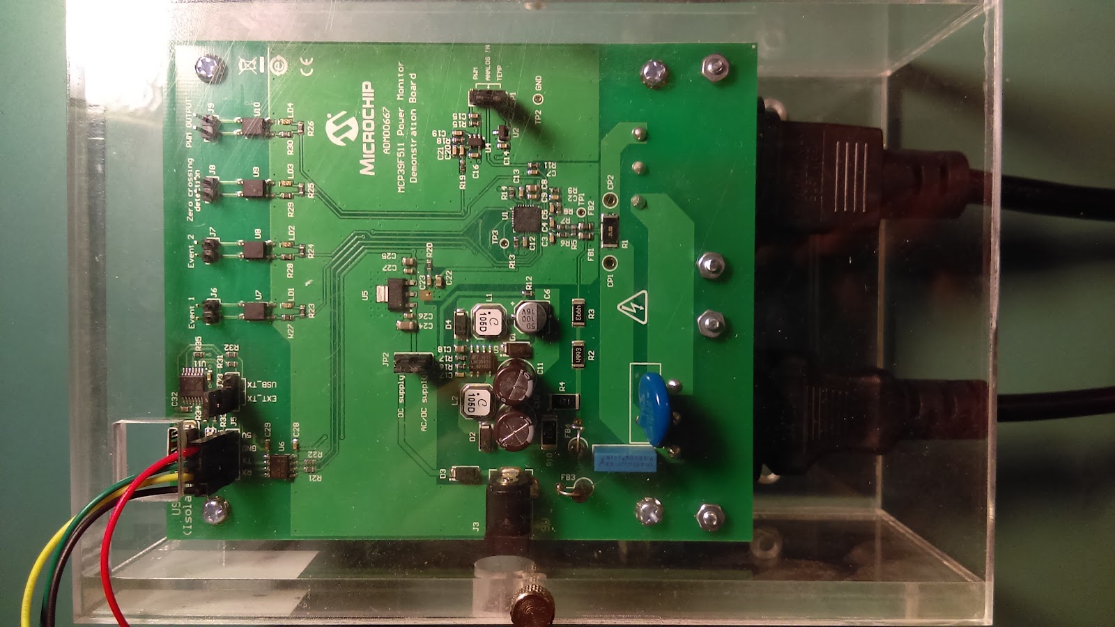
The MCP39F511 was selected as an easy to use power monitoring solution. The MCP39F511 records 16 different values relevant to power consumption. These values include the usual voltage, current, active reactive and apparent power. In addition to these there is also power factor and imported and exported power counters allowing for both power consumed and generated to be accounted for. The MCP39F511 communicates via UART and allows for most of its functionality to be customized to fit your specific application. With a configurable power range as well as minimum accumulated power consumption, this solution is capable of covering a large range of applications. In this project the MCP39F511 is contained in the ADM00667 evaluation kit. The ADM00667 provides isolation between the high and low sides ensuring any control electronics do not get damaged. There are also headers for easy connection to an external UART device to simplify communications with an external controller.


[000280].jpg
MCP39F511 in the ADM00667 Evaluation Lit


In order to upload the data to the selected cloud platform a CC3100 boosterpack is mounted on the MSP430. The CC3100 is WiFi certified and contains a TCP/IP stack as well as various other protocols. This makes the CC3100 a simple solution for connecting to the internet and uploading data to any desired cloud platform. Texas Instruments provides an API for communicating with the CC3100 in C allowing for easy progression to a large scale manufacturable device.


[000290]--9.jpg
CC3100 Simplelink WiFi BoosterPack


Since the CC3100 is a boosterpack that mounts directly on the MSP430F5529 the only wired connections that need to be made are to the MCP39F511. The UART connections provided through the 40-pin headers are used for this purpose. Also because the ADM00667 provides isolation between the high and the low voltage sides 5V needs to be provided to the low side to power the optocouplers. For this an additional connection could be made from the MSP430F529 as long as the CC3100 is mounted under the MSP430F5529. Once these connections are made the hardware is setup and ready to be used.


SOFTWARE

The software for this project was written using C/C++ in the Energia IDE. The simplicity as well as abundance of libraries allowed for a prototype to be up and running in a very short period of time. The code has two main parts, the initialization code found in the setup function and a 6 state, state machine in the loop function. The initialization code sets up a WiFi object, sets the UART baud rate to 115200 bps and initializes two outputs for indicator LEDs. The WiFi connection is used to communicate to the M2X cloud platform. The MSP430 communicates to both the MCP39F511 and the connected PC via UART. This is used for both retrieving data from the MCP39F511 as well as debugging software and communication issues via the PC connection.


Communicating with the MCP39F511

The communication protocol for the MCP39F511 device is based on the Simple Sensor Interface (SSI) protocol. This protocol is used for point-to-point communication from a single-host MCU to a single-slave MCP39F511. It is important to note that the maximum number of bytes in either a receive or transmit frame is 35.


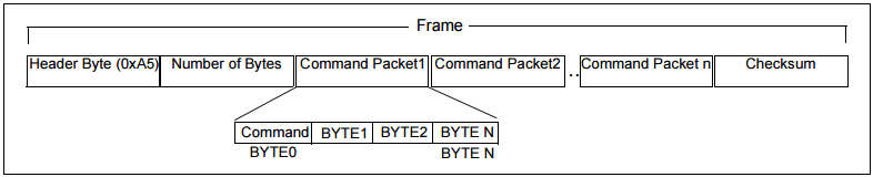
The SSI protocol requires that each message start with a header (0xA5), the number of bytes in the frame, a command byte and a valid checksum.


2016-09-25 21_31_21-MCP39F511 Data Sheet.png
MCP39F511 Packet Format


Every frame that is sent starts with the same header or start byte, 0xA5. The number of bytes in the frame includes the payload as well as the header and checksum bytes. The checksum is generated by adding all bytes in the frame and taking to modulo of 256. There are 10 commands that can be sent to the MCP39F511 that allow for reading and writing to registers, setting and clearing the EEPROM as well as calibrating various functions in the MCP39F511. An issue to be aware of with the MCP39F511 is that although the default baud rate is 115200 bps, the MCP39F511 needs a few microseconds (~300) between every grouping of two bytes.


The MCP39F511 has three device responses. The first is an ACK, this signifies that the frame was received correctly and the commands were executed correctly. The second response is a NAK, this is used to let the host controller know that the frame was received but was either not understood or could not be executed. Lastly there is a CSFAIL response that lets the host know the frame may be correct but the checksum is not and the frame needs to be resent.


Code Generation

The code for this project was started from two other base projects and then rehashed to provide the functionality needed for this project.


The first code base used was the MultiSerial.ino example from Energia. This allowed for basic communication between two different serial devices. In this case the MSP430F5520 would request data from the MCP39F511 via UART and then pass it to a host PC via the UART backchannel. The second code base used was the LaunchPasWiFiPost.ino example from M2X bundled with Energia. This postes a value to the M2X cloud based on the value read from the onboard buttons.


The two projects were then merged once they were determined to be working satisfactory. That is that the MCP39F511 could reliably be polled for data and the data correctly outputted to the PC. Since the data is received LSB first, the bytes first need to swapped to correctly interpret the data. Also the MCP39F511 data sheet does not clearly explain the conversion factors between the measured data and the received data. In order to achieve the correct results trial and error along with the provided “Power Monitoring Utility” were used.


For the M2X demo, the major issue was trying to get multiple data points uploaded simultaneously without having a real time clock. While there apparently is a function to retrieve the server time from the M2X server, Energia had issues finding the correct data types in the M2X library. There is also mention of a single value upload for multiple data streams but again the functionality could not be found in the Energia library. Eventually multiple single value uploads were used decreasing the reliable polling rate for the MCP39F511.


State machine

The system uses a 6 state, state machine of which the last state is a fail case should the WiFi/internet connection be dropped. This case was added after experiencing the issue with the damaged CC3100 in the hope that resetting the connection would resolve the issue. Ultimately this did not resolve the issue with this particular boosterpack but was left in as a preventative measure for other fully functional CC3100 boosterpacks.


The first state is the only state where data is requested from the MCP39F511. In this state the MSP430 sets the address pointer for the MCP39F511 to 0x00 and then requests the next 28 bytes of data. This allows the system to retrieve the values for voltage RMS, line frequency, power factor, current RMS as well as active, reactive and apparent power. Since this request is repeated every 10 seconds an array is used to store this command sequence. This state also sets the green LED high for the duration of requesting data from the MCP39F511 as a visual indicator that the system is working.


The second state looks for an ACK from the MCP39F511. If an ACK is received the state is incremented and the state machine can progress to receiving the number of bytes in the current frame. If there is an issue the MCP39F511 sends back other device responses to indicate the possible issues. The first device response is a NAK, this indicates that the frame was received but the command could not be executed or could not be understood. It is also possible that there was an issue in the command byte. The second possible device response is CSFAIL. In this case the frame again was received but the checksum was incorrect. If either a NAK or CSFAIL are received the state is decremented so that the command can be resent.


The next state (3rd) receives the number of bytes in the frame. This is used in the next state to know how many more bytes need to be received.


The 4th state receives the remaining bytes in the frame. At every iteration through this state the number of bytes received is compared to the number of bytes to be received. Once these numbers are equal the state is incremented. In the current implementation of the software there is no time out or other check to ensure an issue between the MSP430 and the MCP39F511 does not cause the system to hang. There is however a precaution in place to be sure any unread data does not cause ongoing issues by including a Serial.flush at the start of the first state.


The last continually used state is the 5th state which process and sends the retrieved data to the M2X cloud platform. In order to send the data correctly to the cloud the data first needs to be organized correctly. The MCP9F511 returns all data LSB first, therefore the order of the returned bytes needs to be swapped. Before the data can be processed the validity of the received data needs to be checked. To accomplish this the checksum is first calculated and checked. If the received checksum and the locally calculated checksum match then the data is processed. If the checksums do not match, the data is discarded and a new request is issued.


System State Machine with Six States


The code and discoveries in this project were done in a way that hopefully they could easily be reproduced. To better aid in this the full code revision has been uploaded to github. The Git repository for this project can be found here and can be cloned by anyone wanting to add, change or use the code for their own purposes. It should be noted there is a need to add your own WiFi and M2X credentials in the associated WiFi_Credentials.h file.


Moving Forward

The next steps for this project would be to improve the timing resolution. This would need either the addition of a RTC or a connection to a time server. The next major step is to see how this compares to the MangOH Green board to get a better sense of of the comparable capabilities and prototyping time frames.


0a7989e8248c9af5fbf12f6da3e24bd6.png
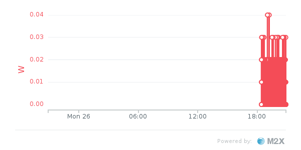
Real Time Power Consumption in Watts


Original post on Element14 can be found here

Wednesday, September 21, 2016

IoT Hardware to Cloud Comparison Project: TI LaunchPad vs Sierra Wireless MangOH Green

too-many-choices1.png


The internet of things (IoT) has become unquestionably the next biggest thing and already has blown up faster then most people could have imagined. As the IoT gains traction more companies will be seeking to to provide IoT components. This market includes everything from ICs and modules to fully connected hardware platforms and all the software in between, as well as the cloud platforms to which remote sensor data is uploaded to and analyzed.


With so many options in the hardware, software and cloud platforms it can often be confusing to decide on one option or even to know why to choose an option. Since this is only becoming an increasingly bigger issue I decided to try and do a comparison between two setups that would accomplish the same task. The task to be implemented would be to monitor power consumption in semi-real time. The data sampled would then be uploaded to the cloud to provide information such as power consumed, line voltage, power factor etc. The success of each system would be judged by the simplicity of getting a prototype running and the possibility to move that into a final product.


Measuring Power Consumption
The MCP39F511 from Microchip was selected to do the power measurements due to its ease of use and availability. Specifically the ADM00667 demonstration board was used since it provides everything needed to use the MCP39F511 without needing to design and build a board. The MCP39F511 can output 11 commonly used values that are tracked and can be easily exported. These values include line voltage, current, power factor, and energy counters among others. For this project the calibration and tuning variables were left unchanged as they provided relatively good values.


ADM00667 Power Demonstration Kit for the MCP39F511


The Hardware
The two hardware platforms selected were the MSP430 Launchpad series from Texas Instruments and the mangOH Green from Sierra Wireless. The MSP430 was selected for its ease of programming (Energia is used in this project) as well as its ability to be upgraded to a full production product with code written in C.


The project was first implemented using the MSP430 Launchpad ecosystem. The platforms looked at here included the MSP430FR5969 and the MSP430F5529. The project initially started with the MSP430FR5969 because of the simpler chip design and lower power consumption in sleep time. Unfortunately the WiFi stack or another portion of the provided connectivity libraries appears to have a bug that causes the system to disconnect after a few transmissions.

MSP430FR5969 With and Without the CC3100 Mounted


This portion of the project was therefore moved to the MSP430F5529. This is a board that has been used before in other Wi-Fi and IoT projects with some success. It was hoped that the current iteration of the libraries would fare better, which thankfully they have.


MSP430F5529 With CC3100 Mounted and UART Connections to MCP39F511


The Wi-Fi connection is provided by the CC3100 BoosterPack. This is an easy to connect board that uses SPI to communicate with the host processor. The board follows TI’s boosterpack standard and therefore easily allows other boards or devices to connect without interference.


CC3100 Boosterpack


The second implementation of the project will use the mangOH Green board from Sierra Wireless. The mangOH board offers a lot of functionality that enables it to easily and reliably talk to various sensors. This includes mangOH IoT connectors, an Arduino compatible connector, USB and RS323 and RJ45 among others. The mangOH also has the ability to communicate over cellular networks removing the need to have a WiFi or ethernet connection. The operating system running on the mangOH is Linux based Legato. This provides the ability to prototype with the mangOH in various software languages.


mangOH Green Development Kit with WiFi and Breakout Expansion Cards Installed


Other hardware platforms were considered but for various reasons were not selected. The ST Discovery platforms were considered but were rejected due to a lack of programming resources available to easily and quickly produce a functional prototype. While mbed does allow for quick prototyping the steps involved in doing so and the need to be online at all times were seen as drawbacks for quick prototyping. Arduino was also an option but, due to the ability to produce the same prototype using Energia and the ability to move past a prototype if needed made the MSP340 series superior for this comparison.


options.gif


The Platform
The cloud platforms looked at include a long list of which only one has been selected for use at this point and one has been tentatively selected by default. Others may be explored in later blogs. The first cloud platform selected is M2X from AT&T. This platform was selected because of it very broad range of supported languages and operating systems. M2X can be used, to name a just a few, on Arduino, mbed, BeagleBone, Raspberry Pi and Energia. M2X also supports languages that include but are not limited to C, Java, Node.js, Python and Ruby. With this wide range of options it allows for a project to be easily implemented on a large range of platforms and software formats. The second cloud platform being considered for review is AirVantage from Sierra Wireless. This was given higher priority due to one of the platforms being used in this review was designed by Sierra Wireless and uses their processor.


In selecting M2X and AirVantage other cloud platforms were looked at but, like in most projects a quick and justifiable decision needed to be made. Below is a list of the platforms looked at and a brief explanation why they weren't used. Since the goal of the project was to produce a prototype in a short period, it should be noted the main reason for rejecting a platform was due the inability to get the correct information quickly and easily.


This platform is currently under review due to one of the selected platforms having been produced by Sierra Wireless and the hope that the two should be easily connected reducing prototyping time.


A brief look showed all supported devices need an OS. This was a big negative considering that most nodes do not need to contain heavy computing power but rather a simple Wi-Fi connection to upload data.


This was an option but could not quickly find how to use WiFi with my device and their service. Good tutorials to get started but in the end the steps needed to get moving were longer than the final choice. This may be looked at again in a later version.


This was also an option but with no easily visible where the data would appear. It also appeared that the data would appear on other platforms that could be easily uploaded to directly. If multiple platforms were going to be used (pull from one and push to another) this would be a great option.


Tago does not provide a way to implement their solution using the desired hardware platforms.


This looked like a great option but again complexity of the website made this a choice to come back to if something simpler could not be found. This may be an option for a later implementation of this project.


This platform provides a REST API that would have been useful but curl is needed. From all the looking around cul needs some form of OS to run correctly. Either way this wasn't a quick prototype option.


Convoluted website, finding something to get started easily and quickly was not possible.


Another convoluted site with a lot of information but nothing to get me to what I needed in a short time or with any reasonable guidance or explanation.


This was by far the most convoluted website. Trying to find just a service that may work for my application was a task. Once this was found, if you do find it, getting any information on how to get up and running quickly is even harder to find if it at all possible. Definitely a platform I would avoid for now.


Original post on Element14 can be found here