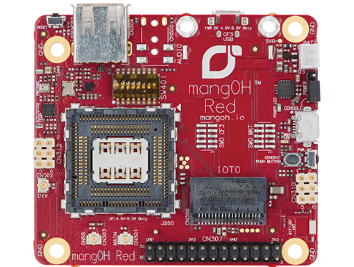
Sierra Wireless has just launched their newest offering in the IoT space. The MangOH Red is a smaller and more compact board than it's older brother the MangOH Green. Aimed at a being used in an end product rather than the development, the board resembles the footprint of the Raspberry Pi. With onboard Bluetooth and WiFi, the MangOH Red is ready to be used in any IoT application. Still standard are the CF3 modules with their on chip cellular connectivity and GLONASS and GPS positioning capabilities. The CF3 module cellular options include 3G, 4G LTE and LTE-m1/NB-IoT modules.
MangOH Hardware
The MangOH Red has a notably different hardware setup from the MangOH Green. Being more compact, the MangOH Red has one CF3 slot and one IoT expansion card slot. Because the MangOH Red has onboard bluetooth and WiFi there is an onboard antenna as well as u.fl connector to allow for an external antenna to be attached for these services. The other previously supported antenna connections (cellular, Glonass and diversity) are all still provided. No longer provided onboard is ethernet, RS323 and the arduino shield connector. For the users who may miss these, they are still available via the IoT expansion cards. The debugging interface has been made simple with a micro USB connector.
New to the MangOH Red are pressure, light and temperature sensors. These new sensors along with the IMU gives the board spacial awareness right out of the box. Also new the the MangOH Red is a Raspberry Pi Hat connector. This allows for the more complex and capable boards designed for use with the Raspberry Pi to be used with the MangOH Red. Built in battery charging and monitoring circuitry allow for a rechargeable battery to be added. With this setup Sierra Wireless has made a product that a true IoT board that is ready to be deployed anywhere monitoring is needed.
Unboxing and Setup
The MangOH Red comes in a neatly packed box with everything you need to get started. One big improvement from the MangOH Green is the inclusion of a universally compatible sim card. With 100MB of data this is enough to get anyone started with the demos and basic applications. Setting up the MangOH Red is quick and easy The WP module is slipped into the module holder and the cover snapped closed. After connecting the cellular antenna all that is left to do is connect the USB cables. These are used to provide power and access to the console. While it is possible to provide power from either USB cable, access to both the console and CF3 module via SSH is useful.
The documentation for the MangOH Red has been revised and updated from the MangOH Green. This new revision has produced a clearer and more concise set of documents. The initial setup time, from out of the box to getting the demos running has been reduced with the aid of better step by step instructions. The “MangOH Red Setup Guide” is especially helpful in getting the system setup and performing its first set of data logging to the cloud.
After everything has been connected the hardware is ready to be used. Upon powering up the system, you will need to work through the getting started guide. This will setup your environment on your PC as well as install the latest applications on the MangOH Red. The only issue encountered was a change in RSA key which the command line explained how to resolve.
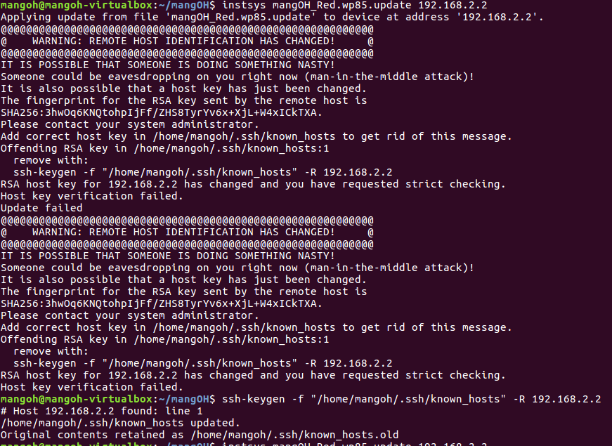
Once done, completing the installation is easy and smooth. The rest of the getting started guide follows the same well explained step by step paradigm. As the rest of the setup and getting started is self explanatory we’ll move to the software structure of Legato used by the MangOH
MangOH Software - Basic Structure
The MangOH boards use the Legato framework as the basis for their software. The Legato framework provides a lot of APIs take care of the simple as well as to simplify the more complex tasks that can be performed with the MangOH boards. The framework, while well thought out and logically ordered, can take some time to get used to for those just starting out. The basic file structure as well as the chain between variables and peripherals will be explained below.
Basic organization of the Legato file structure
The first folder (application folder) acts as a container for the application and is often named with the name of the application. This folder contains the application definition file as well as the component folders. The application definition file (adef) allows the compiler to know what components are used in the application as well as what peripherals are required. The adef also binds external hardware or devices to internally used variables.
Application Definition File (ADEF)
Using a very simple example we will look at the heartbeatRed application. In this application which uses very few resources and has only one component the the adef looks as shown below. Starting from the top, the executables defines what code should be run in this application. In this snippet the heartbeatComponent is what we would like the application to run. Since a component can be run with multiple instances each instance is given a unique name. In the code below there is only one instance named heartbeat. Now that the instance has been named, we let the system know under processes that we would like this instance to be run. To do this we place the instance name heartbeat in the subsection run. This will start the application when the system loads (provided we have put on line 3 “start: auto” and not “start: manual”). If it is set to manual, you will need to do: app start heartbeatRed. Lastly there is the bindings section. This links the external devices (ports, files, etc.) to variables the software can use. In the code below we would like to be able to control pin 34, this is the onboard LED. To accomplish this the variable mangoh_led which is found in the heartbeatComponent and is part of the heartbeat executable is connected to the gpioService. This service through the Legato GPIO service then connects the variable to the specified pin.
sandboxed: true
version: 1.0.0
start: auto
executables:
{
heartbeat = ( heartbeatComponent )
}
processes:
{
envVars:
{
LE_LOG_LEVEL = INFO
}
run:
{
( heartbeat )
}
faultAction: restart
}
bindings:
{
heartbeat.heartbeatComponent.mangoh_button -> gpioExpanderServiceRed.mangoh_gpioExpPin14
heartbeat.heartbeatComponent.mangoh_led -> gpioService.le_gpioPin34
}
|
heartbeatRed adef file as found in the heartbeatRed application folder
Component Definition File (CDEF)
Now that we have shown the compiler what components are to be included as well as what devices are needed and provided a handle for components to access them, let's look at the file that explains how the component is put together. The component definition file (cdef) explains how the various files are integrated as well as what source files the component needs to be correctly compiled.
As mentioned in the adef, we would like to have access to peripherals and as such we have linked a variable to them in the adef. In the cdef we now connect them to an API to allow us to manipulate and interact with these hardware or service components. This is done in the requires section by listing the variable in the api subsection and linking it to the required API. In this code snippet we need access to the gpio API, the mangoh_led variable is therefore linked to the le_gpio.api. The other section in this code snippet lists all the source files needed by the component to function correctly.
requires:
{
api:
{
mangoh_button = ${LEGATO_ROOT}/interfaces/le_gpio.api
mangoh_led = ${LEGATO_ROOT}/interfaces/le_gpio.api
}
}
sources:
{
heartbeat.c
}
|
Component.cdef file as found in the heartbeatComponent folder
Source Code
Let's now have a quick look at the source file that makes up this component and controls how the LED behaves. Below is the full source code for this component it is the code listed in the cdef and used to turn on and off the onboard LED. The first thing to note is the inclusion of both legato.h and interfaces.h. The first allows us to use any of the legato header files used by the component, all legato programs will use some legato header. The second file include.h links in the auto generated header file from the cdef.
Moving further down the code we see in the function LedTimer a variable called mangoh_led_Deactivate, this variable is created through the binding section in the .adef file. In essence this is using the variable mangoh_led, created in the cdef and linked to hardware in the adef, with the api. We are therefore saying the variable mangoh_led should be used with the function call Deactivate to turn off the specified pin. This same principle applies to the other variables in the code that use the legato APIs. The next function, ConfigureGpios sets the pin with the LED attached as an output. If this fails the legato API is then used to send a message to the system log using LE_FATAL_IF. This ability set in the cdef under envVars and allows the system to log messages at the info level and lower.
The last and most important part of the C source file is the COMPONENT_INIT. This is similar to main() in C programs but, because there is no main() in legato applications, we need a different entry point. The COMPONENT_INIT is this entry point. It is important to note though, that unlike main functions this function must return. If COMPONENT_INIT does not return then the rest of the application will not run. In this specific COMPONENT_INIT function a timer instance is created to control the intervals between turning on and off the LED. After an instance is created various parameters for the timer (period, whether to repeat or not as well as its handle) are set. Lastly the gpios are configured using the previously created function and the timer is then started. After all this is done the COMPONENT_INIT is exited and control is handed back to the legato framework.
/**
* @file
*
* Blinks the user controlled LED at 1Hz. If the push-button is pressed, the LED
* will remain on until the push-button is released.
*
* <HR>
*
* Copyright (C) Sierra Wireless, Inc. Use of this work is subject to license.
*/
#include "legato.h"
#include "interfaces.h"
#define LED_TIMER_IN_MS (1000)
static bool LedOn;
static le_timer_Ref_t LedTimerRef;
/*------------------------------------------------------------------------------------------
* Toggle the LED when the timer expires
*/------------------------------------------------------------------------------------------
static void LedTimer(le_timer_Ref_t ledTimerRef)
{
if (LedOn)
{
mangoh_led_Deactivate();
LedOn = false;
}
else
{
mangoh_led_Activate();
LedOn = true;
}
}
/*------------------------------------------------------------------------------------------
* Turn the LED on and disable the timer while the button is pressed. When the button is
* released, turn off the LED and start the timer.
*/------------------------------------------------------------------------------------------
static void PushButtonHandler(bool state, void *ctx) //
{
if (state)
{
LE_DEBUG("turn on LED due to push button");
le_timer_Stop(LedTimerRef);
mangoh_led_Activate();
}
else
{
LE_DEBUG("turn off LED due to push button");
mangoh_led_Deactivate();
LedOn = false;
le_timer_Start(LedTimerRef);
}
}
/*--------------------------------------------------------------------------------------------------
* Sets default configuration LED D750 as on
*/--------------------------------------------------------------------------------------------------
static void ConfigureGpios(void)
{
// Set LED GPIO to output and initially turn the LED ON
LE_FATAL_IF(mangoh_led_SetPushPullOutput(MANGOH_LED_ACTIVE_HIGH, true) != LE_OK, "Couldn't configure LED GPIO as a push pull output");
LedOn = true;
// Set the push-button GPIO as input
LE_FATAL_IF(mangoh_button_SetInput(MANGOH_BUTTON_ACTIVE_LOW) != LE_OK,
"Couldn't configure push button as input");
mangoh_button_AddChangeEventHandler(MANGOH_BUTTON_EDGE_BOTH, PushButtonHandler, NULL, 0);
}
COMPONENT_INIT
{
LedTimerRef = le_timer_Create("LED Timer");
le_timer_SetMsInterval(LedTimerRef, LED_TIMER_IN_MS);
le_timer_SetRepeat(LedTimerRef, 0);
le_timer_SetHandler(LedTimerRef, LedTimer);
ConfigureGpios();
le_timer_Start(LedTimerRef);
}
|
heartbeat.c source file as found in the heartbeatComponent folder
While this was a rather simple and easy to follow demonstration it outlines the most important parts of setting up a legato application. The most complex and important part of this example is how variables are linked to the device or hardware they wish to control. The adef links the device to a variable name. The cdef then links this to an API which the source code can then use to interact with and manipulate the device.
I am planning on releasing another blog post shortly that will explain the more complex redSensorToCloud application. This application has multiple components and uses linux drivers for some of the peripherals.
![[000276].jpg](https://lh3.googleusercontent.com/2poyftBJA3poMxrOtiHeFRyXyVcFevHQV6zEkkkrfZvbEoa0lTyVPNL7i2G_Qioy1GU3VR3XyNQyLgbpwbZpnlzgz2YQYdYPcz-c79cYQ3Koe0VgLur2HBzTxOy_h6fotlzBHjqa)
![[000280].jpg](https://lh6.googleusercontent.com/mB5CqICD4saluKnor6Ze62EbOK7SWj1gk3LuaBop2NduJFKZuZjbjtFG81wSlidqUvXyfaFVNK0p6i0Zr1CWgYwx13jdH_xThoRWyduzm4R0JUtkJFba5toln012kZj8C8SMiDg9)
![[000290]--9.jpg](https://lh4.googleusercontent.com/DPZYfZYf1TrHULI1LVMENBbTGEJ4fBkCRX1IrB0ZaUhoZ1bS8LBSSawE6ERLwOCVyF_g4ArCo3mY8JGASdlKhnyaNFRMzUFTdqRHQk7yodI15Lwh9MkbkclCo8e6I4NOElu9N7NH)