I would like to thank Element14 and TE for selecting me for this roadtest. The Raspberry Pi 2/3 Weather Sensor Shield (DPP904R000) piqued my interest for a couple of reasons. First is my ongoing interest in evaluating sensor suits. Because more companies are producing their own sensors its becoming increasingly more complex to select a sensor. Adding these sensors to my comparison chart would allow for a better understanding of the offering from TE. As an ongoing project a platform, for easy comparison of the data, has not yet been established. The second reason for wanting to review the Weather Sensor Shield is a weather balloon project that is due to be completed by the time the weather is more favourable.
First impressions - Unboxing (Lack Thereof)
The board arrived in a padded envelope and an anti-static bag. While I often prefer minimal packaging this was very much bare bones. Being accustomed to receiving even single components in large boxes this was very unusual. Without even a small box for protection, keeping the sensors safe is that much more complicated. Another point to note was the lack of any documentation. While most products do not ship with lengthy guides they do at least ship with a getting started guide or link to an online document. In this case there was nothing included to get a new user started.
The packaging the board arrived in, a shipping box from Element14, which contained the padded envelope in which was the anti-static bag
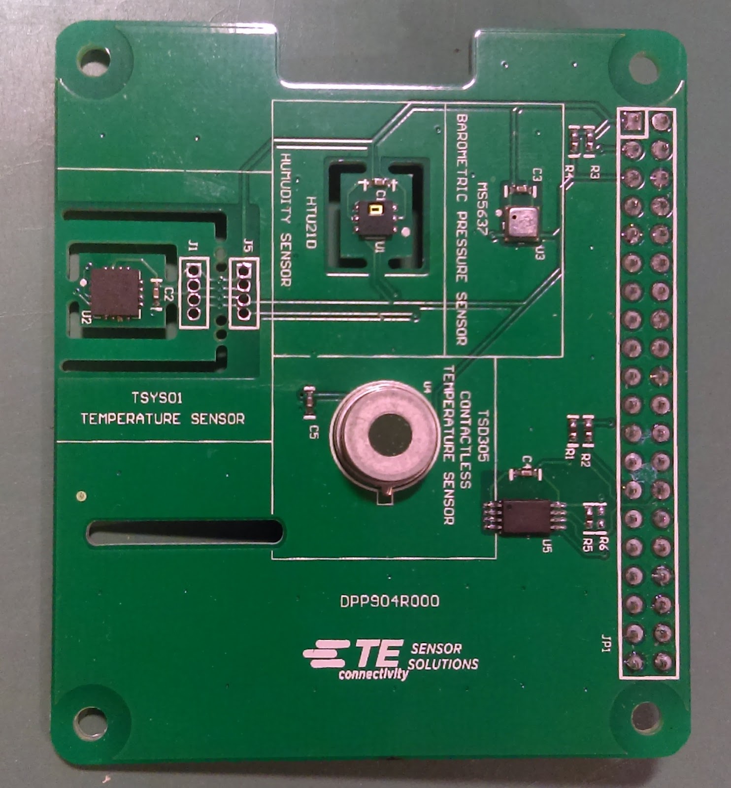
On the positive side the board is well marked. Each of the four sensors are clearly labeled. The connector orientation is also well marked to ensure correct mounting. Overall it is a simple board with ample space around each sensor to prevent thermal and mechanical interference between sensors.
Each sensor is clearly labeled as is pin #1 on the connector
Test Outline
I had outlined a series of tests for this kit to determine how user friendly it is as well as how it performs against its outlined specifications. Unfortunately, due to some issues that will explained, most of these tests could not be completed before writing this review.
The test procedure I had outlined for DPP904R000 contained approximately 5 individual tests. These ranged from the usual to those definitely not intended for this kit. The tests outlined in the proposal where as such:
Due to mainly documentation complications only the first two test have been conducted so far. As more progress is made further updates will be added.
Platform Compatibility
Physical Compatibility
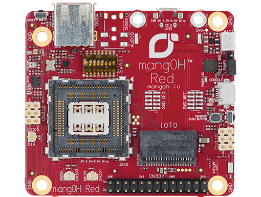
The first test was to see if the DPP904R000 is compatible with with other platforms that have a Raspberry Pi connector. The board selected to test this kit with was the MangOH Red from Sierra Wireless.
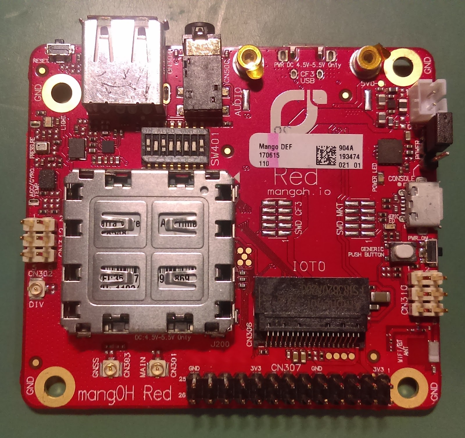
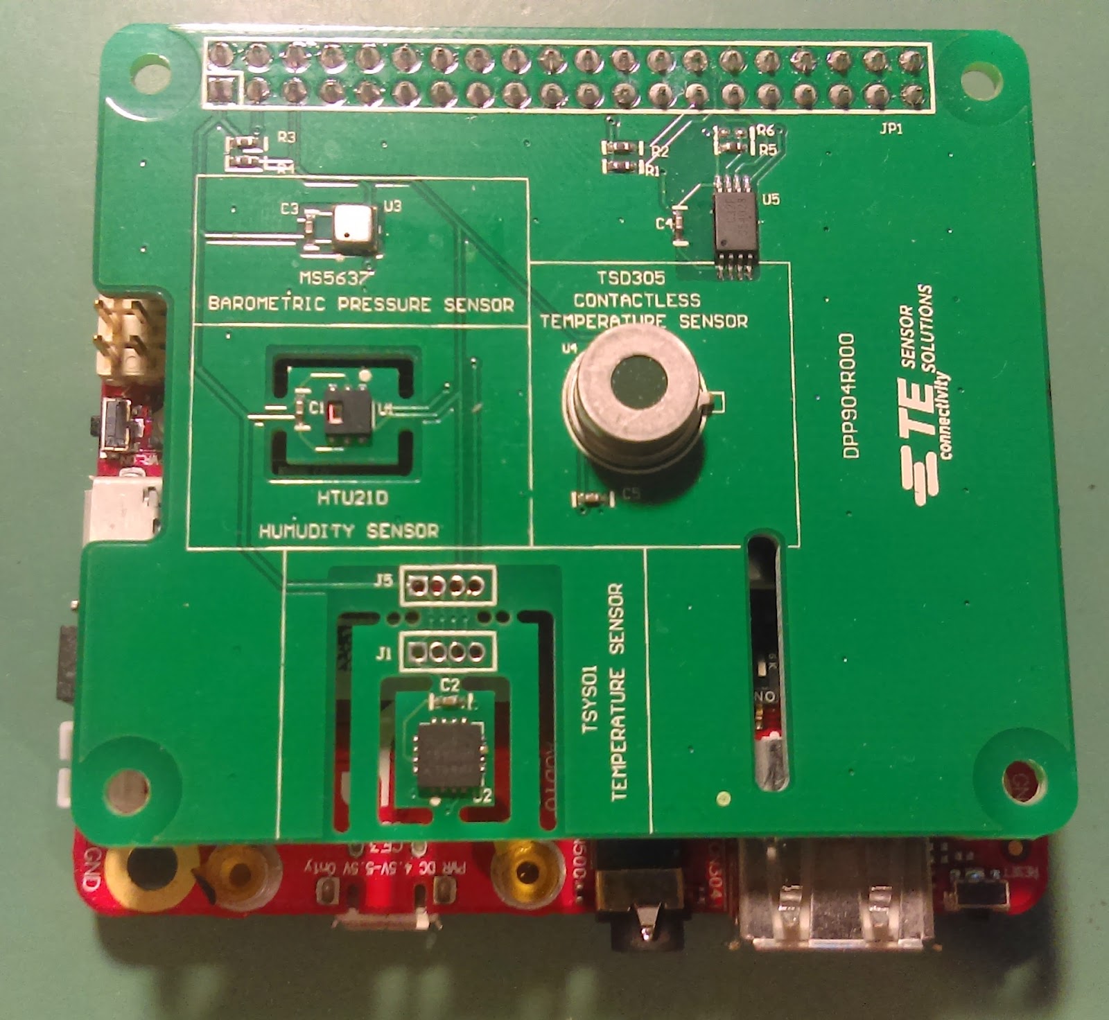
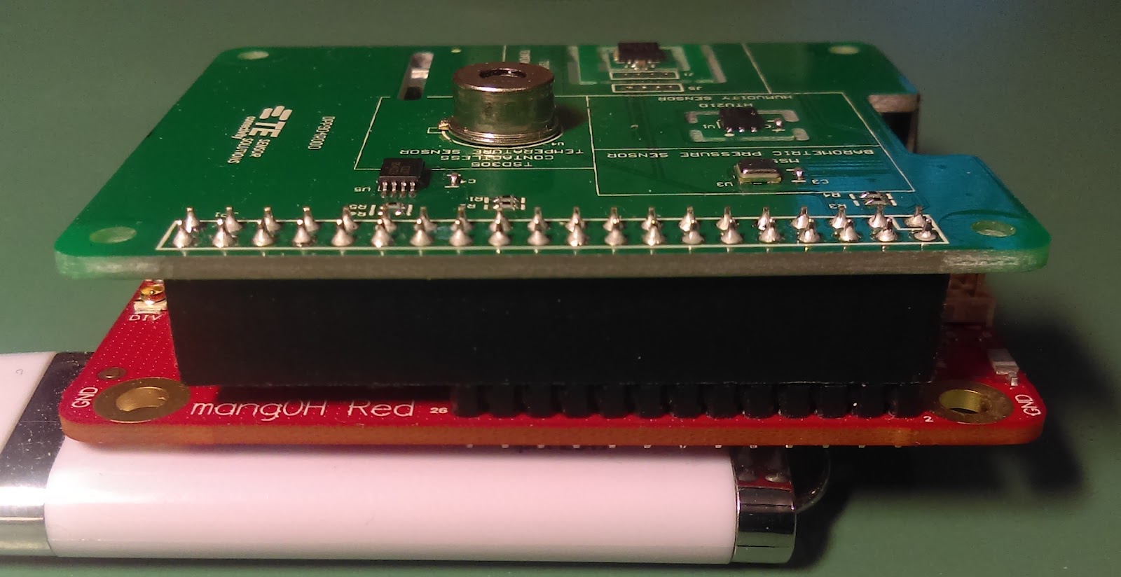
This board has a 26 pin instead of a 40 pin, Raspberry Pi connector. Even with this, only two of the six pins used are not supported. These two pins are apparently used by the Raspberry Pi to read a shields ROM chip for identification purposes. Since the ROM is not used with the MangOH Red, it would not be a concern.
Communication Compatibility
Using terminal commands to test the basic compatibility between the boards was the next step before moving to any of the other tests. This would also be the first time the documentation was consulted in detail. Any product that survives needs good documentation or support. This is where the Raspberry Pi Weather Sensor Shield started to have issues.

- How easy would it be to use this with another platform
- Can we get the calibration data from the PROMs easily and reliably
- Does the data from various sensors match up (they each have a temperature sensor)
- Can these sensors survive the outdoor environment, in a sheltered but not sealed enclosure
- Can the needed calculations be carried out on a microcontroller without overloading the system
- What is the true power consumption of these sensors
- What is the theoretical maximum altitude that can be measured with the pressure sensor (taking temperature as well as air pressure into account)
Due to mainly documentation complications only the first two test have been conducted so far. As more progress is made further updates will be added.
Platform Compatibility
Physical Compatibility
The first test was to see if the DPP904R000 is compatible with with other platforms that have a Raspberry Pi connector. The board selected to test this kit with was the MangOH Red from Sierra Wireless.
MangOH Red from Sierra Wireless
This board has a 26 pin instead of a 40 pin, Raspberry Pi connector. Even with this, only two of the six pins used are not supported. These two pins are apparently used by the Raspberry Pi to read a shields ROM chip for identification purposes. Since the ROM is not used with the MangOH Red, it would not be a concern.
The DPP904R000 mounted on the MangOH Red, only 26 of 40 pins make contact
Communication Compatibility
Using terminal commands to test the basic compatibility between the boards was the next step before moving to any of the other tests. This would also be the first time the documentation was consulted in detail. Any product that survives needs good documentation or support. This is where the Raspberry Pi Weather Sensor Shield started to have issues.
i2cdetect shows 0x76 is reserved by the system and that only the TSD305 at 0x1E is detected
The first sensor tested was the HUT21D humidity sensor. This sensors has an easy to follow communication structure. Shortly after reading the datasheet humidity data was being reported back. This quick victory gave a positive feeling towards the Raspberry Pi Weather Sensor Shield, sadly this victory was short lived.

The HTU21D humidity sensor with thermal isolation
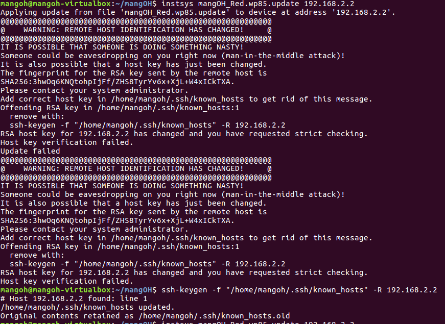
The second sensor to be used with the MangOH Red was the TSYS01. The address listed for the TSYS01 temperature sensor is 0x76 and 0x77 depending on whether the CSB is pulled high or low. Since the MangOH Red has a sensor (BMP280) at 0x76 the TSYS01 sensor could not be reached at this address. However, because the TSYS01 can change its I2C address, there was hope. Looking at the schematics it was revealed that TE did not design this option into their board. While cost could have been a factor ($0.03 for the 0𝛀) there are ways around this (Freescale now NXP, is great at giving options without increasing cost). Unfortunately because of this, the TSYS01 is unusable with the MangOH Red. It would later be discovered that in fact the address could not be changed without causing another conflict.
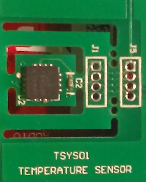
The TSYS01 temperature sensor with multiple layers of thermal isolation
The next sensor to be checked for compatibility was the TSD305. While even bad hardware can be made to work with great documentation, no hardware can work with no documentation. This was in essence the case with the TSD305.
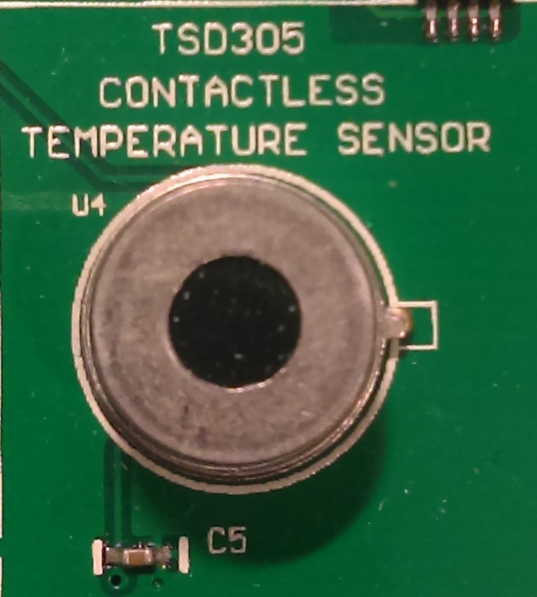
The TSD305 contactless temperature sensor
The datasheet lists the address as 0x00. Interestingly Raspbian (which this board is specifically made for) and other Linux distributions, reserve this address and so its not accessible to the userspace. This left this sensor unusable until I was lead to TE’s GitHub repository. Initially I was shown python drivers, while I was working in the terminal and C this was still more promising than the documentation. Looking through the files it became clear the correct address for the TSD305 is 0x1E. Due to receiving this information rather late, no further testing was conducted with this sensor.

Datasheet displaying 0x00 as the sensor address
The last sensor to be tested was the MS5637 pressure sensor. Following the sequence of steps need to complete a measurement it is unclear what addresses need to be written/read to/from. At issue are the large number of address available write too. Whether reading pressure or temperature data there are 6 different registers that can be written too, each with a different OSR value. Compounding the matter, is the lack of explanation regarding OSR or how it affects the measurements. Choosing one of these at random the data still needs to be read from the ADC. With no mention of one or two ADCs, at first glance is unclear what address each data point should be read from. Through more careful reading it can be inferred that there is in fact only one ADC.
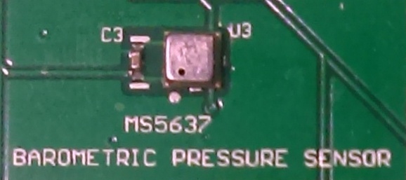
The MS5637 pressure sensor
Once the sequence of events were clarified an attempting to connect with the MS567 was made. The address for the MS5637 is listed as 0x76. As previously noted, this address is already used by the TSYS01. Besides this address not being incompatible with the MangOH Red, its not compatable with the TSYS01 on the same board (DPP904R000 ). With the unclear sequence of steps along with the an incorrect device address, this device’s documentation is the worst of the four sensors on the DPP904R000 .

Datasheet displaying 0x76 as the sensors address
As mentioned with the TSD305, the driver files do contain usable information. Very disappointingly TE carried over their mistake from the documentation to the repository. While the hex value is listed as 0x77, which is correct, no one checked the binary value copied over to notice it is in fact 0x76.
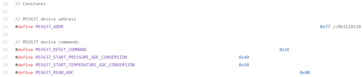
The define statement for MS5637_ADDR lists the address as 0x77 and 0b1110110 which are not the same value
This leads to another issue. Why would TE select address for different sensors to be the same. Regarding the ability to change address the TSYS01 documentation states “Therefore, two TSYS01 can be interfaced in the same I2C bus”. How can this be so, if the application requires a pressure sensor the second address would be consumed by the MS5637. With 124 address available TE selected two separate sensors that could easily be used in the same application to have overlapping addresses.
Easy of Use with Higher Level Code
The sequence of steps needed to conduct a measurement for these sensors are not necessarily very efficient. The HUT21D requires the system to wait for the measurement to complete before receiving a response. During this time there are two options available. The first option is to wait while the HUT21D holds the SCL line low. This prevents anyone else from using the I2C bus. It may also hold up the system depending how the code is implemented. The second option is to poll the HUT21D waiting for an ACK. While this allows others to use the I2C bus it does require the system to poll the sensor. The other three sensors only provide polling as an option to retrieve data. A better and more efficient option would be to implement an interrupt pin. While this could still require polling in some systems, the time needed to do so would be reduced from milliseconds clock cycles.
This may not be an problem in some systems and even more so in the systems that appear to be targeted by TE. However in low power or time critical systems the extra cycles can reduce battery life or the ability to process data ontime. This would lead to a contradiction in the claim to low power yet the need to use more power to execute and retrieve a measurement.
Documentation and GitHub Repository
As previously noted the documentation for these sensors is lacking, some more than others. There is both missing information as well as clearly incorrect information. The biggest issue found working through these datasheets was the with the TSD305. In this case the sensor address was incorrectly listed as 0x00 instead of 0x1E. Other less critical omissions are lack of explanations or clarifications on how the sensors behave. The most noticeable of these is the OSR values in the MS5637 datasheet. Also unclear in this datasheet is the number of ADCs, the relevance is whether or not there are multiple addresses to read from or not. This though can be clarified with a more careful reading of the datasheet.
One thing that that is very helpful and allows a user to achieve the stated accuracy quickly are the worked examples. The datasheets for each sensor has a fully worked example from capturing the ADC value to computing the actual measured value. Even the simplest of sensors, the HUT21D, has simulated input data that is then converted. This gives a user real values to run through the code to check the calculations with.
Possibly the biggest omission in the documentation is the mention of a GitHub repository for these sensors. This repository contains generic C and python drivers. Also in the repository are demos and drivers for Arduino. The complication here appears to be two different product pages for the same product. The page linked from Google as well as some of the vendors does not mention GitHub or IBM BlueMIX. However, another page found does, under “Related Materials”, mention both of these resources. Also at issue is, while these are mentioned in the datasheet for the DPP904R000, it is done so at the bottom where most companies put their copyright and revision information. This means its in a place a decent number of users will not look.
This lack of exposure puts TE’s sensors at a disadvantage over other sensors. While other companies are showing off the drivers for their sensors, TE is not effectively letting users know theirs exist.
Next Steps
Moving forward I am looking to complete my testing with this board. Once completed the data should be available in real time to compare with other sensors in my lab environment. Beyond this is the hope to be able to integrate the sensors (excluding the TSYS01) in the weather balloon project. This would help to determine how reliable they are in such an application as well as how altitude affects them. Included in this is a test to see what is the maximum altitude that the MS5637 can reliably report.
Conclusion
From the limited amount of testing possible with the DPP904R000 it can be said this board is mostly compatible with other platforms. At issue is TE’s decision to not take advantage of the ability to change the I2C addresses where possible. This not only limits its compatibility with the MangOH Red but, potentially with other boards that may be used in conjunction with it. Indeed it is true that this would not help on this board, that is because TE has decided to allocate overlapping addresses to different sensors. Why TE would select address that potentially conflict with their own sensors is baffling at least and self harmful at worst.
The documentation also for the most part does allow for a developer to complete his task. The problem here is the extra time needed to do so due to missing or incorrect information. With a few fixes this could easily and quickly be resolved. Along the same lines is to fix the product pages. Not just the page of the DPP904R000 but of each sensor to include a link to the GitHub and IBM BlueMIX pages.
Once these obstacles are resolved the DPP904R000 would be a great product to work with for most applications. Not included in this category would be time critical and potentially power sensitive applications. The stated accuracy, factory calibration make for a reliable sensor for indoor environmental sensing applications.
Original post on Element14 can be found here