Showing posts with label Web control. Show all posts

Wednesday, October 4, 2017

MangOH Red Launch and Legato Framework


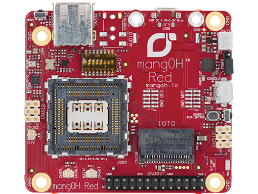
Sierra Wireless has just launched their newest offering in the IoT space. The MangOH Red is a smaller and more compact board than it's older brother the MangOH Green. Aimed at a being used in an end product rather than the development, the board resembles the footprint of the Raspberry Pi. With onboard Bluetooth and WiFi, the MangOH Red is ready to be used in any IoT application. Still standard are the CF3 modules with their on chip cellular connectivity and GLONASS and GPS positioning capabilities. The CF3 module cellular options include 3G, 4G LTE and LTE-m1/NB-IoT modules.

MangOH Hardware

The MangOH Red has a notably different hardware setup from the MangOH Green. Being more compact, the MangOH Red has one CF3 slot and one IoT expansion card slot. Because the MangOH Red has onboard bluetooth and WiFi there is an onboard antenna as well as  u.fl connector to allow for an external antenna to be attached for these services. The other previously supported antenna connections (cellular, Glonass and diversity) are all still provided. No longer provided onboard is ethernet, RS323 and the arduino shield connector. For the users who may miss these, they are still available via the IoT expansion cards. The debugging interface has been made simple with a micro USB connector.

New to the MangOH Red are pressure, light and temperature sensors. These new sensors along with the IMU gives the board spacial awareness right out of the box. Also new the the MangOH Red is a Raspberry Pi Hat connector. This allows for the more complex and capable boards designed for use with the Raspberry Pi to be used with the MangOH Red.  Built in battery charging and monitoring circuitry allow for a rechargeable battery to be added. With this setup Sierra Wireless has made a product that a true IoT board that is ready to be deployed anywhere monitoring is needed.

Unboxing and Setup

The MangOH Red comes in a neatly packed box with everything you need to get started. One big improvement from the MangOH Green is the inclusion of a universally compatible sim card. With 100MB of data this is enough to get anyone started with the demos and basic applications. Setting up the MangOH Red is quick and easy The WP module is slipped into the module holder and the cover snapped closed. After connecting the cellular antenna all that is left to do is connect the USB cables. These are used to provide power and access to the console. While it is possible to provide power from either USB cable, access to both the console and CF3 module via SSH is useful.

The documentation for the MangOH Red has been revised and updated from the MangOH Green. This new revision has produced a clearer and more concise set of documents. The initial setup time, from out of the box to getting the demos running has been reduced with the aid of better step by step instructions. The “MangOH Red Setup Guide” is especially helpful in getting the system setup and performing its first set of data logging to the cloud.

After everything has been connected the hardware is ready to be used. Upon powering up the system, you will need to work through the getting started guide. This will setup your environment on your PC as well as install the latest applications on the MangOH Red. The only issue encountered was a change in RSA key which the command line explained how to resolve.
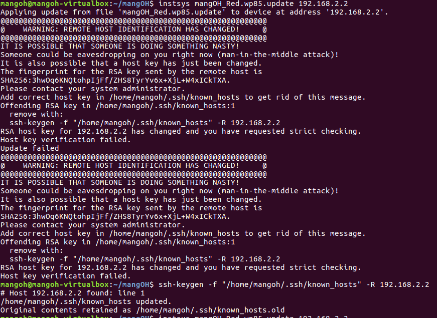


Once done, completing the installation is easy and smooth. The rest of the getting started guide follows the same well explained step by step paradigm. As the rest of the setup and getting started is self explanatory we’ll move to the software structure of Legato used by the MangOH

MangOH Software - Basic Structure

The MangOH boards use the Legato framework as the basis for their software. The Legato framework provides a lot of APIs take care of the simple as well as to simplify the more complex tasks that can be performed with the MangOH boards. The framework, while well thought out and logically ordered, can take some time to get used to for those just starting out. The basic file structure as well as the chain between variables and peripherals will be explained below.

Basic organization of the Legato file structure

The first folder (application folder) acts as a container for the application and is often named with the name of the application. This folder contains the application definition file as well as the component folders. The application definition file (adef) allows the compiler to know what components are used in the application as well as what peripherals are required. The adef also binds external hardware or devices to internally used variables.

Application Definition File (ADEF)

Using a very simple example we will look at the heartbeatRed application. In this application which uses very few resources and has only one component the  the adef looks as shown below. Starting from the top, the executables defines what code should be run in this application. In this snippet the heartbeatComponent is what we would like the application to run. Since a component can be run with multiple instances each instance is given a unique name. In the code below there is only one instance named heartbeat. Now that the instance has been named, we let the system know under processes that we would like this instance to be run. To do this we place the instance name heartbeat in the subsection run. This will start the application when the system loads (provided we have put on line 3 “start: auto” and not “start: manual”). If it is set to manual, you will need to do: app start heartbeatRed. Lastly there is the bindings section. This links the external devices (ports, files, etc.) to variables the software can use. In the code below we would like to be able to control pin 34, this is the onboard LED. To accomplish this the variable mangoh_led which is found in the heartbeatComponent and is part of the heartbeat executable is connected to the  gpioService. This service through the Legato GPIO service  then connects the variable to the specified pin.

sandboxed: true
version: 1.0.0
start: auto

executables:
{
   heartbeat = ( heartbeatComponent )
}

processes:
{
   envVars:
   {
       LE_LOG_LEVEL = INFO
   }
   run:
   {
       ( heartbeat )
   }
   faultAction: restart
}

bindings:
{
   heartbeat.heartbeatComponent.mangoh_button -> gpioExpanderServiceRed.mangoh_gpioExpPin14
   heartbeat.heartbeatComponent.mangoh_led -> gpioService.le_gpioPin34
}
heartbeatRed adef file as found in the heartbeatRed application folder

Component Definition File (CDEF)

Now that we have shown the compiler what components are to be included as well as what devices are needed and provided a handle for components to access them, let's look at the file that explains how the component is put together. The component definition file (cdef) explains how the various files are integrated as well as what source files the component needs to be correctly compiled.
As mentioned in the adef, we would like to have access to peripherals and as such we have linked a variable to them in the adef. In the cdef we now connect them to an API to allow us to manipulate and interact with these hardware or service components. This is done in the requires section by listing the variable in the api subsection and linking it to the required API. In this code snippet we need access to the gpio API, the mangoh_led variable is therefore linked to the le_gpio.api. The other section in this code snippet lists all the source files needed by the component to function correctly.

requires:
{
   api:
   {
       mangoh_button = ${LEGATO_ROOT}/interfaces/le_gpio.api
       mangoh_led = ${LEGATO_ROOT}/interfaces/le_gpio.api
   }
}

sources:
{
   heartbeat.c
}
Component.cdef file as found in the heartbeatComponent folder

Source Code

Let's now have a quick look at the source file that makes up this component and controls how the LED behaves. Below is the full source code for this component it is the code listed in the cdef and used to turn on and off the onboard LED. The first thing to note is the inclusion of both legato.h and interfaces.h. The first allows us to use any of the legato header files used by the component, all legato programs will use some legato header. The second file include.h links in the auto generated header file from the cdef.

Moving further down the code we see in the function LedTimer a variable called mangoh_led_Deactivate, this variable is created through the binding section in the .adef file. In essence this is using the variable mangoh_led, created in the cdef and linked to hardware in the adef, with the api. We are therefore saying the variable mangoh_led should be used with the function call Deactivate to turn off the specified pin. This same principle applies to the other variables in the code that use the legato APIs. The next function, ConfigureGpios sets the pin with the LED attached as an output. If this fails the legato API is then used to send a message to the system log using LE_FATAL_IF. This ability set in the cdef under envVars and allows the system to log messages at the info level and lower.
The last and most important part of the C source file is the COMPONENT_INIT. This is similar to main() in C programs but, because there is no main() in legato applications, we need a different entry point. The COMPONENT_INIT is this entry point. It is important to note though, that unlike main functions this function must return. If COMPONENT_INIT does not return then the rest of the application will not run. In this specific COMPONENT_INIT function a timer instance is created to control the intervals between turning on and off the LED. After an instance is created various parameters for the timer (period, whether to repeat or not as well as its handle) are set.  Lastly the gpios are configured using the previously created function and the timer is then started. After all this is done the COMPONENT_INIT is exited and control is handed back to the legato framework.      

/**
* @file
*
* Blinks the user controlled LED at 1Hz. If the push-button is pressed, the LED
* will remain on until the push-button is released.
*
* <HR>
*
* Copyright (C) Sierra Wireless, Inc. Use of this work is subject to license.
*/

#include "legato.h"
#include "interfaces.h"

#define LED_TIMER_IN_MS (1000)

static bool LedOn;
static le_timer_Ref_t LedTimerRef;

/*------------------------------------------------------------------------------------------
* Toggle the LED when the timer expires
*/------------------------------------------------------------------------------------------
static void LedTimer(le_timer_Ref_t ledTimerRef)
{
   if (LedOn)
   {
       mangoh_led_Deactivate();
       LedOn = false;
   }
   else
   {
       mangoh_led_Activate();
       LedOn = true;
   }
}

/*------------------------------------------------------------------------------------------
* Turn the LED on and disable the timer while the button is pressed. When the  button is
* released, turn off the LED and start the timer.
*/------------------------------------------------------------------------------------------
static void PushButtonHandler(bool state, void *ctx) //
{
   if (state)
   {
       LE_DEBUG("turn on LED due to push button");
       le_timer_Stop(LedTimerRef);
       mangoh_led_Activate();
   }
   else
   {
       LE_DEBUG("turn off LED due to push button");
       mangoh_led_Deactivate();
       LedOn = false;
       le_timer_Start(LedTimerRef);
   }
}

/*--------------------------------------------------------------------------------------------------
* Sets default configuration LED D750 as on
*/--------------------------------------------------------------------------------------------------
static void ConfigureGpios(void)
{
   // Set LED GPIO to output and initially turn the LED ON
   LE_FATAL_IF(mangoh_led_SetPushPullOutput(MANGOH_LED_ACTIVE_HIGH, true) != LE_OK, "Couldn't configure LED GPIO as a push pull output");
   LedOn = true;

   // Set the push-button GPIO as input
   LE_FATAL_IF(mangoh_button_SetInput(MANGOH_BUTTON_ACTIVE_LOW) != LE_OK,
"Couldn't configure push button as input");

   mangoh_button_AddChangeEventHandler(MANGOH_BUTTON_EDGE_BOTH, PushButtonHandler, NULL, 0);
}

COMPONENT_INIT
{
   LedTimerRef = le_timer_Create("LED Timer");
   le_timer_SetMsInterval(LedTimerRef, LED_TIMER_IN_MS);
   le_timer_SetRepeat(LedTimerRef, 0);
   le_timer_SetHandler(LedTimerRef, LedTimer);

   ConfigureGpios();

   le_timer_Start(LedTimerRef);
}
heartbeat.c source file as found in the heartbeatComponent folder

While this was a rather simple and easy to follow demonstration it outlines the most important parts of setting up a legato application. The most complex and important part of this example is how variables are linked to the device or hardware they wish to control. The adef links the device to a variable name. The cdef then links this to an API which the source code can then use to interact with and manipulate the device.

I am planning on releasing another blog post shortly that will explain the more complex redSensorToCloud application. This application has multiple components and uses linux drivers for some of the peripherals.

Monday, April 11, 2016

Building a Smart Home on a Budget - Hook

Hook-Budget-Home-Automation-System.jpg


Introduction

Today the internet of things is everywhere and in anything yet it has no defined protocol or standardization of any type. This lack of conformity has led to an increasingly growing issue that of incompatibility. This issue mixed with the cost of investing in one manufacturer over another with no guarantee of product life or growth makes for a very precarious technology moving forward.


The group from Hook has decided to challenge this by removing one of the variables in the complexity equation. They have decided to make other manufactures devices the main extension of their own technology. This allows for a end user to choose the device of their choice at the price point of their choosing with only one requirement, it has a RF connection. This is infact Hooks motto “Hook - Smart home on a Budget”


Why test this product

This product was chosen to be tested based on its claims and that it offered the potential to integrate many home automation devices into one system at an affordable price. Every few weeks there is a new home automation system on the market by a new group looking to do something innovative. The issue of incompatibility and cost is constantly growing and with the often included RF link the Hook holds the potential to link all of these devices.


First Impressions  

The Hook is a clean and unobtrusive device that does not take up a lot of space. With the power coming from a provided USB charger the Hook can easily be used in different regions. The LED lighting combinations are a low cost and easy to understand way of letting the user understand what the device is doing.


When I opened the box for the first time, granted the beta release had no housing or casing of any type, I was unsure what I was really looking at. But after plugging the unit in and getting it up and running it becomes clear very quickly that this is a device with no complexities. The Hook is a device that is made to control home automation devices and do that one task well.


Hook  Setup and Usability

The Hook has two methods by which devices can be controlled, the phone app (Android and iOS) and a web app. This combination allows for the Hook as well as the automation devices to be easily configured whether you have a compatible phone or not. The interface is also intuitive and suggestive in that it walks you through the steps needed to setup the Hook and add devices without making the user feel ignorant.


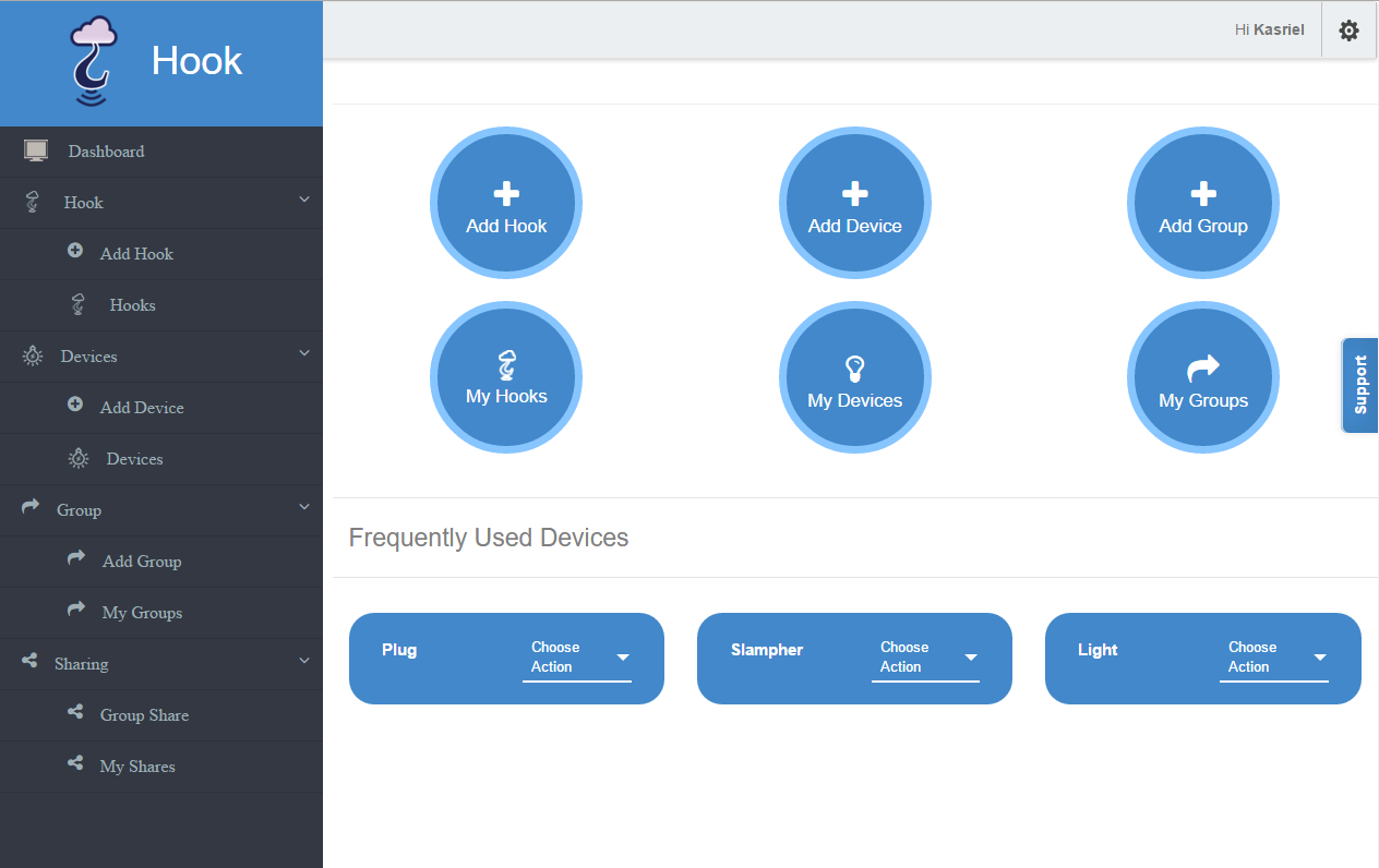
In the web app logging into your account presents you with your dashboard where you can add Hooks, devices as well as other do other actions such as create groups and turn devices on and off.


Screenshot_2016-04-08-13-25-22.png
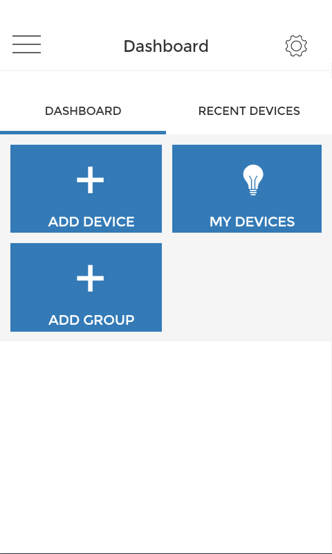
Hook Android app dashboard


2016-04-04 17_13_21-Program Manager.png
Hook web app dashboard


Adding a Hook

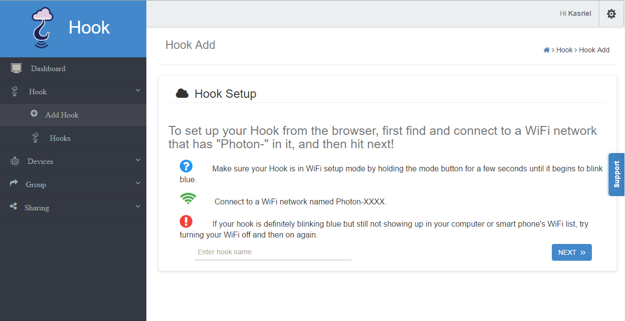
Adding a Hook starts by clicking “Add Hook” which takes you to a page where the steps needed to connect your Hook are clearly outlined and well explained.


2016-04-04 17_04_29-Program Manager.png
Adding Hook using the web app


On the side of the Hook press the button until the LED flashes blue, connect your PC to the Hooks WiFi hotspot add a name and press next. The Hook will then look for WiFi connections around it and ask you to choose one and input the password for that network. After reconnecting to the original network (wait for your PC to connect automatically after the Hook has closed its hotspot) press save. If successful a popup window will let you know.


The last step is a bit of an issue as not waiting long enough before disconnecting has caused the setup to fail a number of times hence the suggestion to wait for the hotspot to be terminated. After bringing this to the attention of the Hook team they have resolved the issue by only allowing the Save button to be active once the device that is used to set up the look is back online. The other issue is the duration between pressing send and the pop up window informing you the setup was or was not successful. With no indication to inform the user that something is infact happening the casual user will press the send button a number of times potentially causing the setup to fail. Again after bringing this to the attention of the Hook team they have decided to look into it and potentially solve the issue by disabling the save button after pressing it the first time.


Once these two pitfalls where discovered and pointed out to other users I was testing the Hook with, the ability to add the Hook to their environment was incredibly simple.


Adding a Device

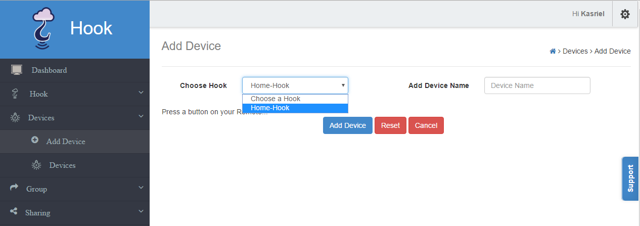
After the Hook is added devices or end nodes need to be added. This is done also from the dashboard and is just as simple. Clicking on “Add Device” presents the you with a screen to choose the Hook you want to add the device too.


2016-04-04 17_17_42-Program Manager.png
Adding a device to Hook using the web app


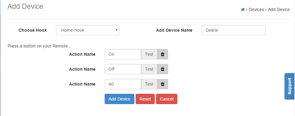
Once you have chosen the Hook and named your device all that is left to do is to press the buttons on the RF remote and the Hook will remember the RF frequency and sequence needed to mimic that button. Each button can be named to better explain its functionality when adding a device that may have multiple buttons.


2016-04-04 17_37_26-Hook _ Add Device.png
Naming a device and its related actions using the web app


The one downside to this method of adding controls is the need to be physically close to the Hook during setup. This is due to the lack of sensitivity in the receiver used by the Hook to record the RF sequence. As this is a one time deal this is really a non issue as the setup can be done with the hook plugged in close to the point of setup and then moved once the setup is completed.


Screenshot_2016-04-05-13-43-26.png
Devices added to the Hook on Android


2016-04-08 14_37_35-Hook _ Devices.png
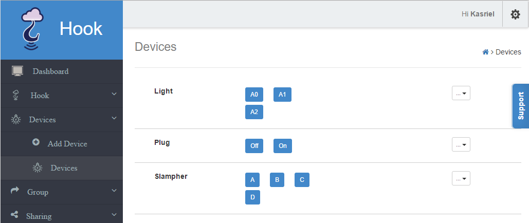
Devices added to the Hook on web app


After all the devices you would like to add have been added you can group devices into groups. Currently this is an issue with devices that use the same button twice. The only workaround is to add that device twice (not the full remote but each device) calling the one device On and the second Off, this method is untested but should work according to my understanding of the system. The Hook team is aware of this issue and will have a fix (toggle switches) rolled out shortly.


IFTTT

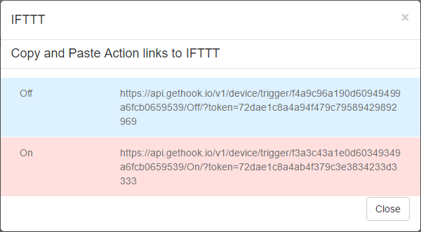
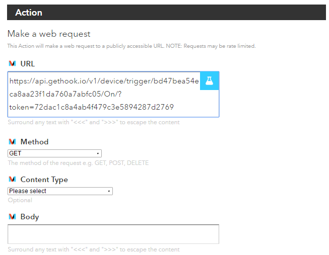
The Hook works with IFTTT (If This Than That) which allows for simple devices to be used in ways well beyond what they were intended for. Without a dedicated IFTTT action (this is in the works) the Hook team has provided a REST API to use with the Maker action. This allows various stimuli to affect any one of the devices connected to the Hook. With dozens of possible stimuli the options for automating your devices seem almost endless. The steps to accomplish this are provided in a blog entry by the Hook team.


2016-04-08 13_09_28-Hook _ Devices.png
REST command to use with Maker Action


2016-04-08 13_07_12-Recipe 35292043 - IFTTT.png
Setting up IFTTT to trigger a Hook device


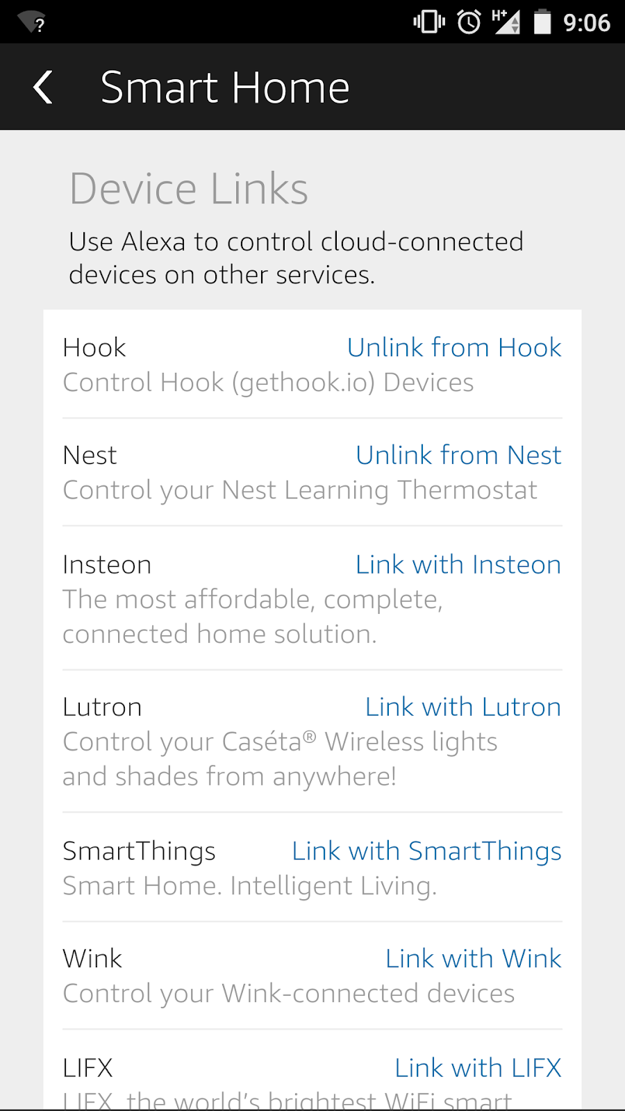
Another feature currently in Beta is the Amazon Echo, this would extend the use of your simple RF devices beyond what some expensive WiFi modules can currently do. Amazon Echo along with IFTTT have the potential to truly help your low cost devices make your home a smart home.


Screenshot_2016-04-08-09-06-10.pngScreenshot_2016-04-08-09-08-13.png
Using Hook with Amazon Echo


Power consumption

As a device that is used to both automate the home and as well as make it smarter it is important to see what the true cost and smarts of such a device are. Part of this cost and intelligence is the amount of power the unit consumes on a daily basis. Since the Hook is used to control other devices and needs to be on at all times the overall power consumption needs to be low for it to be worth its constant use.


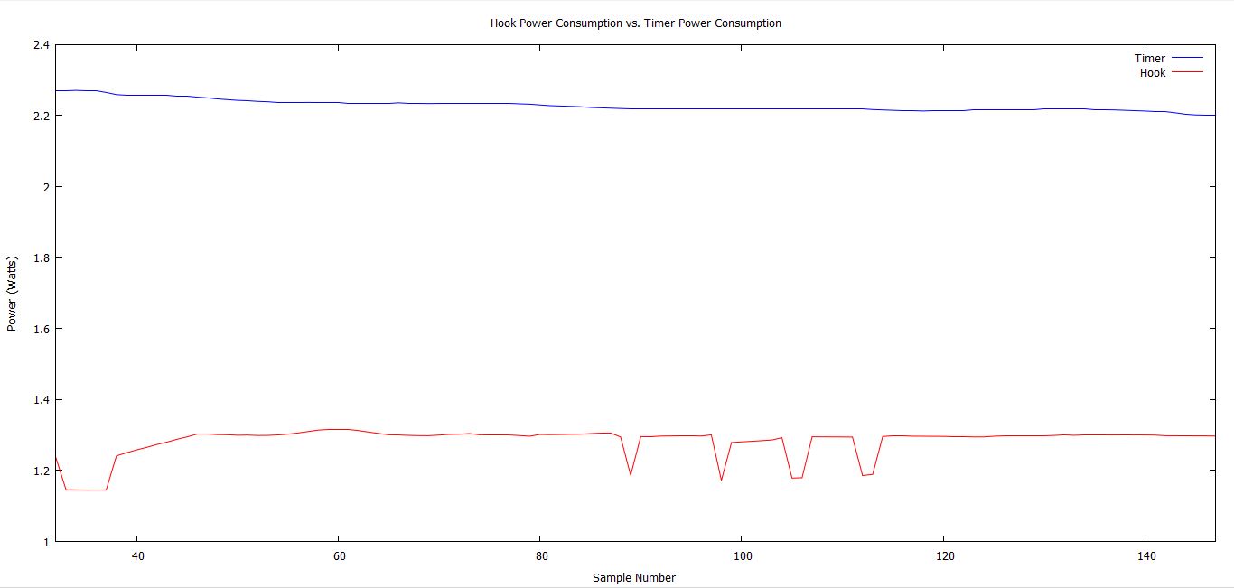
For this the Hook was plugged into a PA1000 (generously lent to me by Tektronix specifically for IoT device testing). The Hook was then left to run for a short duration in various modes. It was this data that was then used to determine the overall power consumption on the Hook. After taking the average the Hook only uses 1.12W, which for a full year is approximately 9.8kWhrs. While this may sound like a lot, it's approximately half of a timer used to turn on and off appliances in your home.


Hook vs Timer.jpg
Hook Power Consumption vs Timer Power Consumption


Reliability

The Hook has been tested over an extended period now and in various conditions. There has been little issue with the Hook in all cases. The only issue found was rapid repeated power cycling (more than 5 times) which cause the Hook to lock up temporarily. This is by no means normal use and should not be done with electronics but it was an issue that was noticed.


Other tests included extended durations unpluged to simulate power outages, moving between WiFi networks and adding to new network (after deleting from account). In all of these cases there was no issue noticed with the Hook. Range has also been tested in a standard home size for Canada. Once a decent spot in the house was chosen, somewhere close to the middle (vertically and horizontally) there were no issues with range or having a previously responsive node not respond.


Setup issues

The setup procedure for the Hook I was given had some issues as it was a beta unit that had been added to another account. Once this was discovered and was added to my list of known “issues” it was easy to move the Hook between accounts.


The big issue was adding the Hook to my account this was found to be impossible after numerous attempts due to an issue on my side. The router I use for testing has connection issues. That is a device can connect to the router but can't always access the internet seemingly due to overlapping IP addresses or its in ability to allocate valid IP addresses. Once I moved to another router that had no such issues the Hook setup and connected to my acount first time with no issue. Based on this I would recommend if any issues are discovered first attempt to use a different router or check the router setup to be sure it is correct before looking at the Hook.  


Concerns

There is little of concern with the Hook other than the usual privacy. I have not looked at what is passed between the PC setting the Hook and the Hook itself. I would assume it is encrypted and secure but this will need to be looked at a later date.


The only issue that stood out was the account security from the backend. During the troubleshooting with the Hook team, where I finally realized it was my issue and not theirs, they were at one point able to add the Hook to my account. This did make me wonder what access the Hook team has to my account and devices and their usage. They were also able to determine that the Hook was not online at one point.


What security is on the backend and how passwords are stored (both account and WiFi networks) I am not sure but this is not just an question with Hook but with all IoT devices used both in the home and out. If any information is passed on from the Hook team or from my own testing, I will add it at a later date.


Answers From Hook

Regarding secure communication between the Hook, the PC and the cloud Hook responded: all communication between the Hook and the cloud uses AES-128 bit encryption and those between the PC and the Hook use HTTPS ensuring all data is kept secret.


Regarding passwords and WiFi details Hook Responded: account password has to be stored on cloud, so that you can use same account across devices. WiFi credentials are saved locally on Hook. They are not even not available to read through a physical connection.


Lastly regarding adding HooK to my account and knowing it is online Hook responded: We used the hook sharing feature to add the Hook to your account, it's a standard supported feature where a user can share the hook with another user. Also each Hook pushes a heartbeat to our servers thus we know if it is online or not.


Moving Forward

Having used the Hook for over a month now in both stand alone mode as well as with IFTTT overall I am very happy with it. I have incorporated other devices I have (Sonoff and Slamphor) with it to bring everything to one central environment. I am looking to integrate with this, through IFTT, environmental sensors to turn on fans when CO2 or humidity levels get too high in my home. This is currently done with a device called LiV Pi but Hook will also be releasing a sensor API sometime in the summer (~June -  August).


Another step currently being looked into is the integration with X10. For those not in North America this should work out of the box as 433MHz is already supported. Unfortunately for those in North America X10 uses 310MHz (closer to 312.85MHz when tested). Since both X10 and the Hook use the same protocol for communication, if a 310MHz RF module that is compatible with the Hook can be located, this integration will also be attempted and tested.


Conclusion

The Hook is an interesting and useful idea that when used with all its abilities can truly bring the home or office to life. This with its intuitive interface and availability from both a phone or browser makes for a truly easy to use and convenient system. Adding in the IFTTT extension, the Hook really allows anyone to set the environment to react and behave in away that works for their unique situation. Lastly knowing that the Hook team has shipped all the Hooks promised to their backers gives me confidence that this is a viable product that has great potential and the ability to keep moving forward in its space of both home automation and IoT. Also having taken every issue I have mentioned seriously and fixing them promptly, Hook is a product that wants nothing more than to be easy for you to use so sign up for the next round of orders and get yours today.


More pictures here:
Upcoming reviews and info here: